Sensor-based image(s) integrity determination system, device, and method

a technology of integrity determination and sensor, applied in the field of aircraft vision systems, can solve the problems of 341 deficiency or insufficient to meet, and the interference of passive sensors, i.e. energy absorption

Active Publication Date: 2016-12-27
ROCKWELL COLLINS INC
View PDF2 Cites 9 Cited by
  • Summary
  • Abstract
  • Description
  • Claims
  • Application Information

AI Technical Summary

Benefits of technology

[0013]Embodiments of the inventive concepts disclosed herein are directed to a system, device, and method for determining the integrity of sensor-based image(s) from image data acquired by one or more passive image sensors and im

Problems solved by technology

As such, passive sensors are subject to interference (i.e., an absorption of energy) from different meteorological conditions as compared with active sensors.
The minimum architecture suggested by DO-341 may be deficient or inadequate to meet the expected system availability and integrity requirements to support landing and rollout operations in the low visibility conditions of 300 feet RVR.
The deficiencies in the architecture may include, but are not limited to, (1) an inability to detect and isolate system faults is a dual sensor system (i.e., the system cannot vote between numerous sen

Method used


Image

  • Sensor-based image(s) integrity determination system, device, and method
  • Sensor-based image(s) integrity determination system, device, and method
  • Sensor-based image(s) integrity determination system, device, and method

Examples


Embodiment Construction

[0029]In the following description, several specific details are presented to provide a thorough understanding of embodiments of the invention. One skilled in the relevant art will recognize, however, that the invention can be practiced without one or more of the specific details, or in combination with other components, etc. In other instances, well-known implementations or operations are not shown or described in detail to avoid obscuring aspects of various embodiments of the invention.

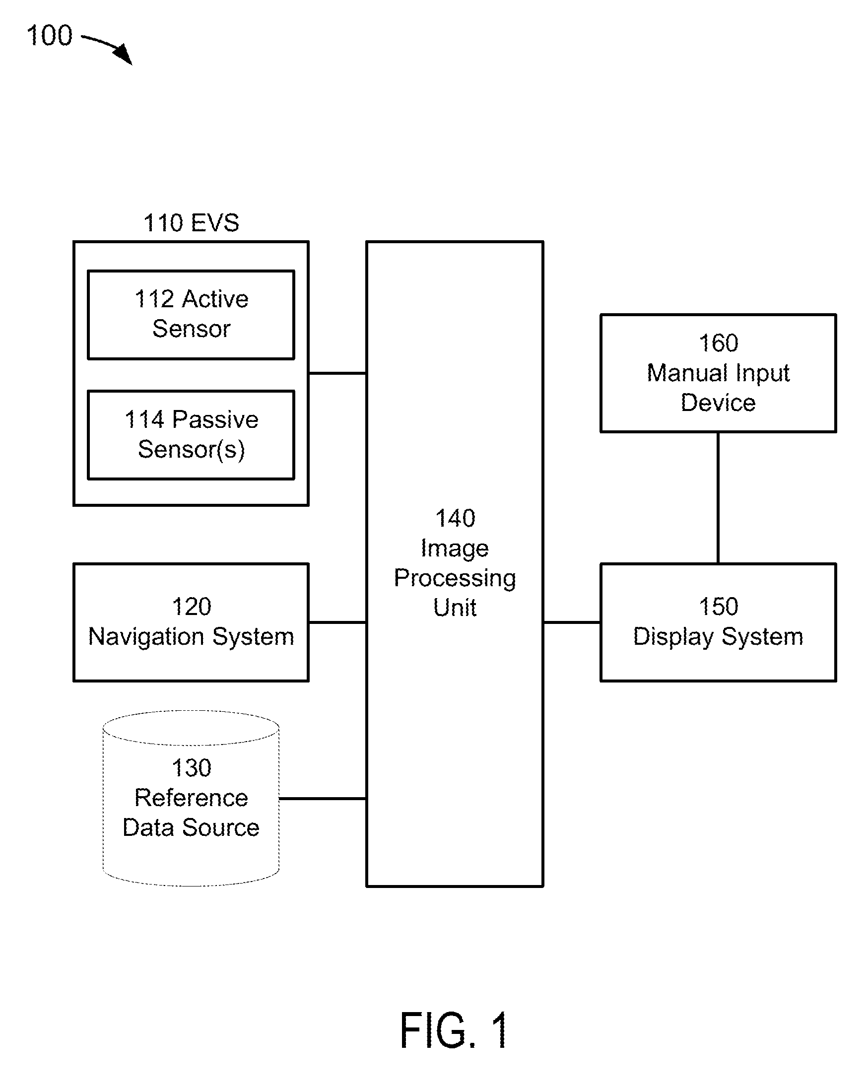
[0030]FIG. 1 depicts a block diagram of a sensor-based image(s) integrity determination system 100 suitable for implementation of the techniques described herein. The system 100 of an embodiment of FIG. 1 may be comprised of an enhanced vision system (“EVS”) 110, a navigation system 120, a reference data source 130, an image processor unit (“IPU”) 140, a display system 150, and a manual input device 160.

[0031]The EVS 110 may be any system, sub-system, or component thereof which could generate enhanc...


PUM


Abstract

A system, device, and method for determining the integrity of sensor-based image(s) are disclosed. The integrity determination system may include one or more sources of passive sensor-based image data, one or more sources of an active sensor-based image data, and an image processing unit (“IPU”). The IPU may receive passive sensor-based image data; receive active sensor-based image data; and (1) determine the integrity of at least the passive sensor-based image data by comparison of the passive sensor-based image data with the active sensor-based image data, and/or (2) combine the passive sensor-based image data with the active sensor-based image data to produce third image data from which a pilot may manually determine the integrity of the first image data.

Description

BACKGROUND OF THE INVENTION[0001]Field of the Invention[0002]This invention pertains generally to the field of aircraft vision systems that present flight information to the pilot or flight crew of an aircraft.[0003]Description of the Related Art[0004]It is well-known that a Synthetic Vision System (“SVS”) may generate image data representative of a synthetic, three-dimensional perspective of a scene in front of the aircraft. When provided to a display system, the synthetic image could be presented on the screen of a display unit. In addition, it is well-known that an Enhanced Vision System (“EVS”) may generate image data representative of the real-world as an enhanced image of the scene in front of the aircraft, where such image data has been acquired by one or more fixed or steerable forward-looking image capture devices.[0005]One purpose of the EVS is to provide imagery of the terminal area and runway environment to the flight crew during times when meteorological conditions prev...

Claims


Application Information

Patent Timeline
IPC IPC(8): H04N7/00H04N7/18
CPCH04N7/183
Inventor MCCUSKER, PATRICK D.TIANA, CARLO L.PETERSON, MICHAEL A.
Owner ROCKWELL COLLINS INC
Why Eureka
Try Eureka