Electric assist device for a bicycle and electrically assisted bicycle provided with such a device

Active Publication Date: 2017-01-03
MICHELIN & CO CIE GEN DES ESTAB MICHELIN
View PDF42 Cites 7 Cited by
  • Summary
  • Abstract
  • Description
  • Claims
  • Application Information

AI Technical Summary

Benefits of technology

[0040]FIG. 11: diagrammatic side view of a conventional bicycle.
[0041]The figures represent different general and detailed views of preferred embodiments of an electric assist device and an electrically assisted bicycle in acc

Problems solved by technology

This type of device has the disadvantage of a high mass, this mass being moreover located at the level of the wheel, which means that the cyclist is very sensitive to it.
Moreover, if the wheel must be removed, for example to change the tire or to repair a puncture, removing the wheel is complicated by the presence of electrical connections that are necessary for powering the ele

Method used


Image

  • Electric assist device for a bicycle and electrically assisted bicycle provided with such a device
  • Electric assist device for a bicycle and electrically assisted bicycle provided with such a device
  • Electric assist device for a bicycle and electrically assisted bicycle provided with such a device

Examples


Embodiment Construction

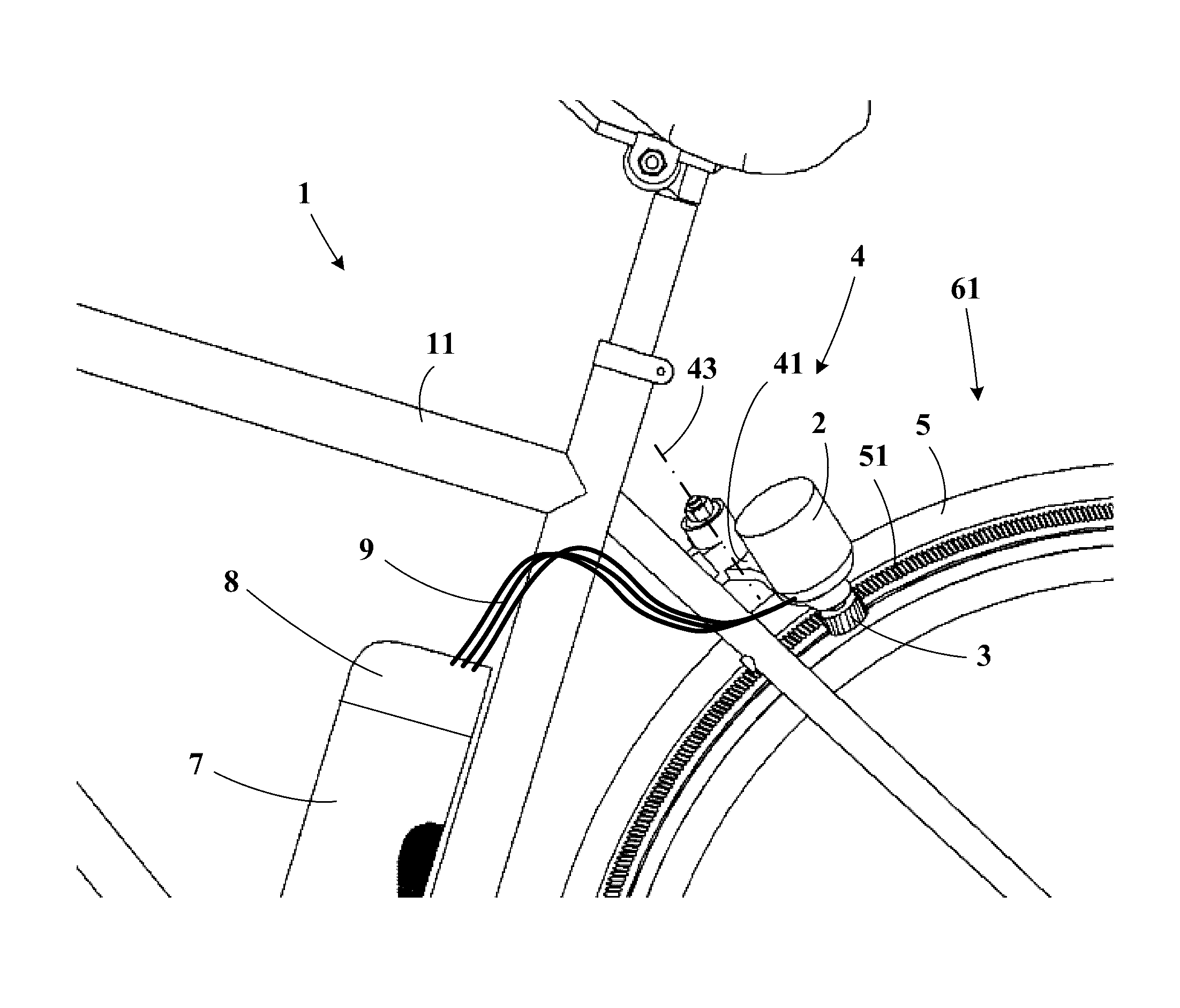
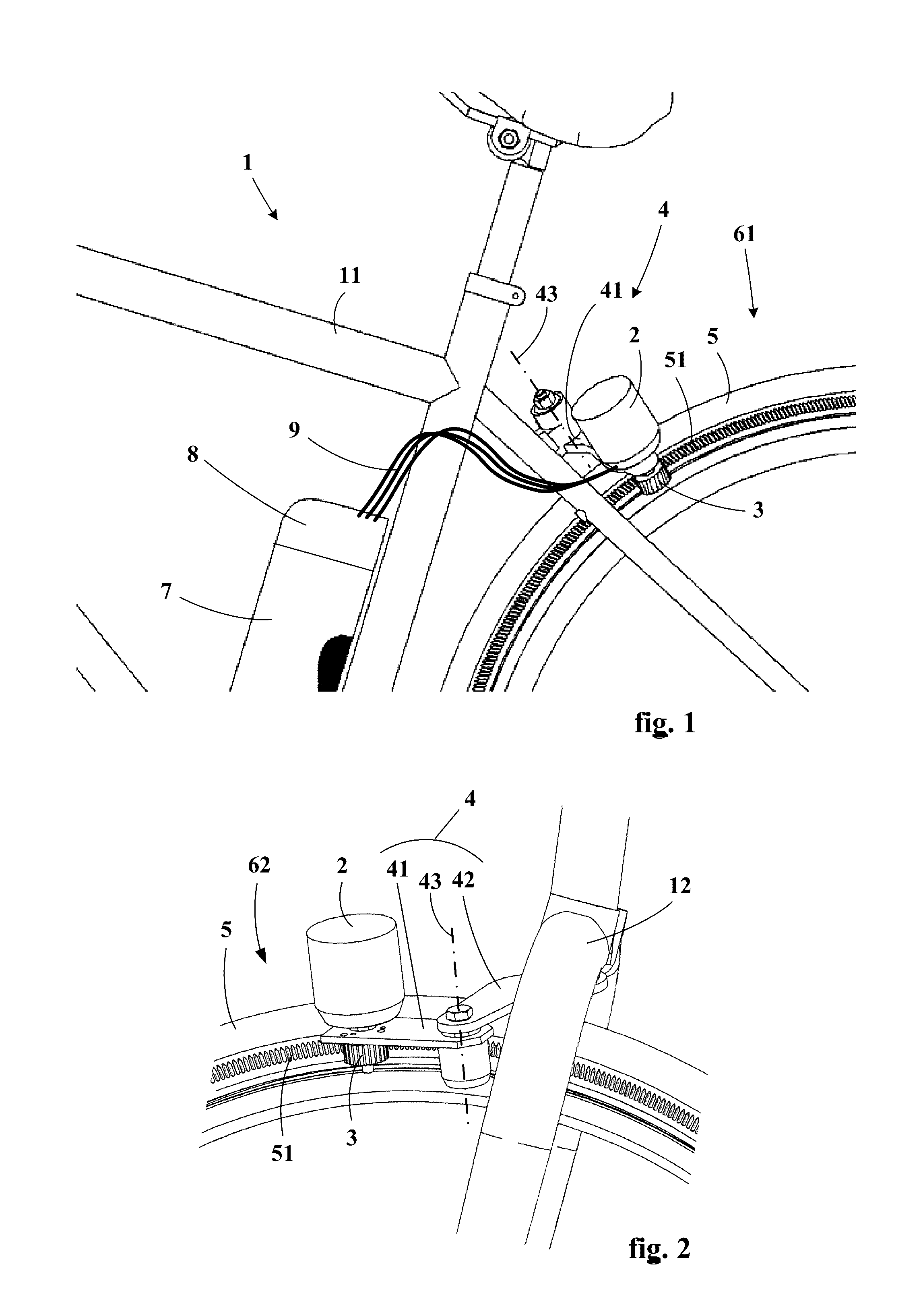
[0042]A conventional bicycle 1′ is shown in FIG. 11. In FIG. 1 are seen the principal elements of an electrically assisted bicycle 1 in accordance with the invention. An electric machine 2 is fixed to the frame 11 of the bicycle 1 in the vicinity of a tire 5, here in the vicinity of the tire of the rear wheel 61. A source of electrical energy, here a battery 7, powers the electric machine via control means 8. The drive pinion 3 meshes tangentially with teeth 51 of the tire 5 and can therefore transmit to it a drive force that assists the cyclist.

[0043]FIG. 2 represents another embodiment in which the electric assist device is intended to cooperate with the tire of the front wheel 62 of the bicycle. There are seen better in this figure the fixing means 4 of the electric machine 2. The fixing means preferably comprise an oscillating arm 41 articulated to a fixed support 42 about an axis 43 substantially parallel to the shaft of the electric machine. The support 42 is fastened to the b...


PUM


Abstract

An electrical assist device is provided for a bicycle. The device includes an electric machine, a drive pinion, an attachment device, a source of electrical energy, and a controller. The attachment device fixes the electric machine to the bicycle near a tire of a wheel of the bicycle. The source of electrical energy powers the electric machine. The controller controls the electric machine. The electric machine includes a rotor, which drives the drive pinion. The drive pinion includes teeth structured to mesh tangentially with complementary teeth fastened to the tire.

Description

FIELD OF THE INVENTION[0001]The present invention concerns electric assist devices for bicycles and bicycles equipped with such devices.RELATED ART[0002]In this field, a certain number of devices available on the market are known.[0003]Some of these devices use an electric machine placed in the hub of one of the wheels of the bicycle. This electric machine drives the wheel directly or via a reducer system. This type of device has the disadvantage of a high mass, this mass being moreover located at the level of the wheel, which means that the cyclist is very sensitive to it. Moreover, if the wheel must be removed, for example to change the tire or to repair a puncture, removing the wheel is complicated by the presence of electrical connections that are necessary for powering the electric machine and specific fixings of the hub that are necessary to transfer the drive torque.[0004]Other devices use a motor-gearbox driving the pedals of the bicycle and therefore using the existing tran...

Claims


Application Information

Patent Timeline
IPC IPC(8): B62M6/75
CPCB62M6/75
Inventor OLSOMMER, DAVIDESSINGER, OLIVIER
Owner MICHELIN & CO CIE GEN DES ESTAB MICHELIN
Why Eureka
Try Eureka