
Refrigerator having a defrost heater

a defrost heater and refrigerator technology, which is applied in the direction of defrosting, lighting and heating apparatus, domestic cooling apparatus, etc., can solve the problems of uneven defrosting and the inability to distribute the heat emitted by the defrost heater evenly in the evaporator, and achieve reliable defrosting and efficient defrosting

Inactive Publication Date: 2017-01-03
BSH BOSCH & SIEMENS HAUSGERAETE GMBH
View PDF26 Cites 0 Cited by
  • Summary
  • Abstract
  • Description
  • Claims
  • Application Information

AI Technical Summary

Benefits of technology

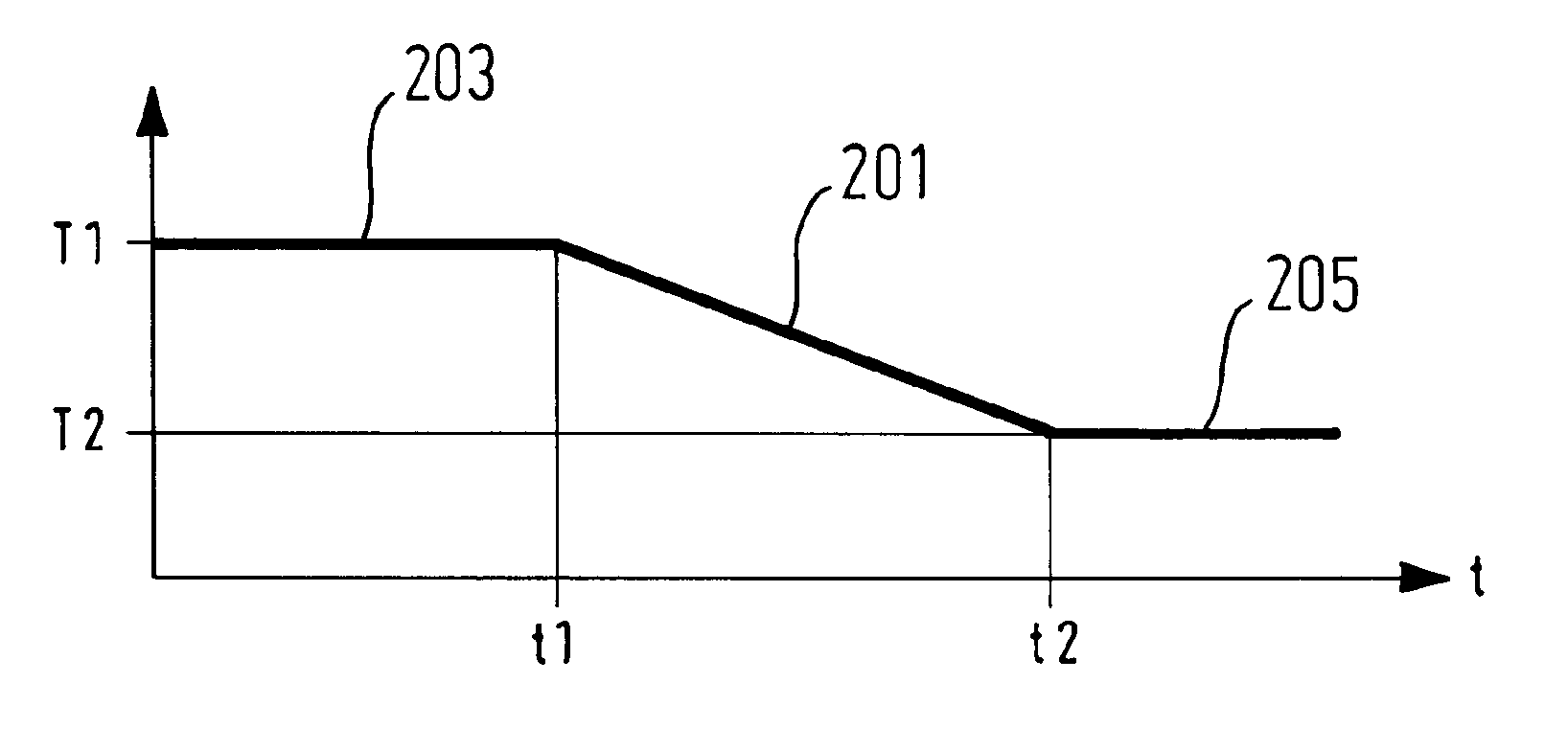
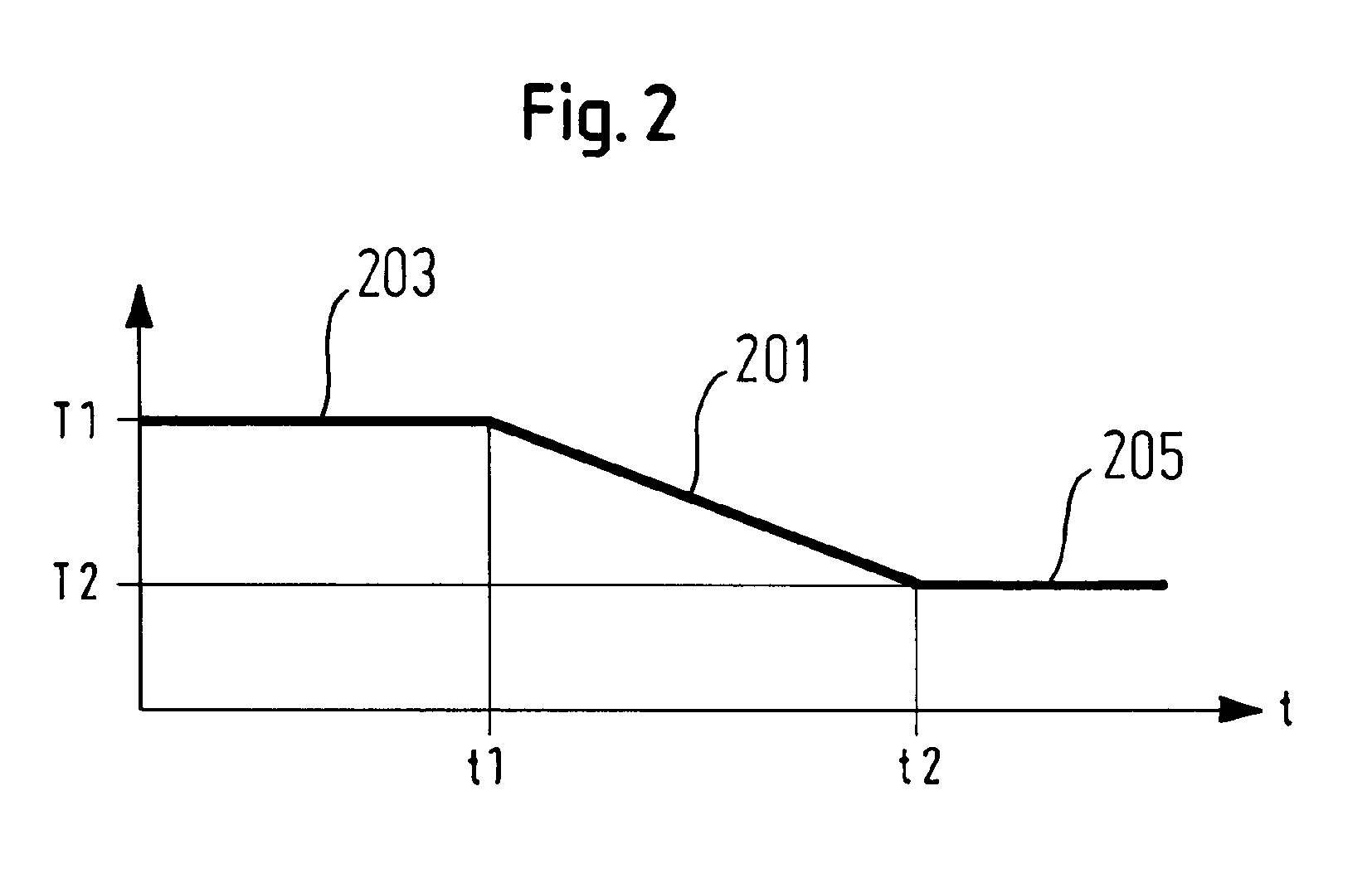
This invention is based on the idea that effective defrosting can be achieved by using multiple predetermined temperatures during the defrost process. By starting with a higher temperature to ensure reliable defrosting in the evaporator, the invention allows for efficient defrosting that saves energy. Additionally, a lower temperature can be set to ensure even heat distribution in the evaporator during the longer defrost period. Overall, this invention helps achieve efficient and reliable defrosting.

Problems solved by technology

However if the preset final defrost temperature is reached too quickly, the heat emitted by the defrost heater cannot be distributed evenly in the evaporator.
This means that the unwanted ice is not thawed at a point further away from the temperature sensor, resulting in uneven defrosting.

Method used


Image

  • Refrigerator having a defrost heater
  • Refrigerator having a defrost heater
  • Refrigerator having a defrost heater

Examples


Embodiment Construction

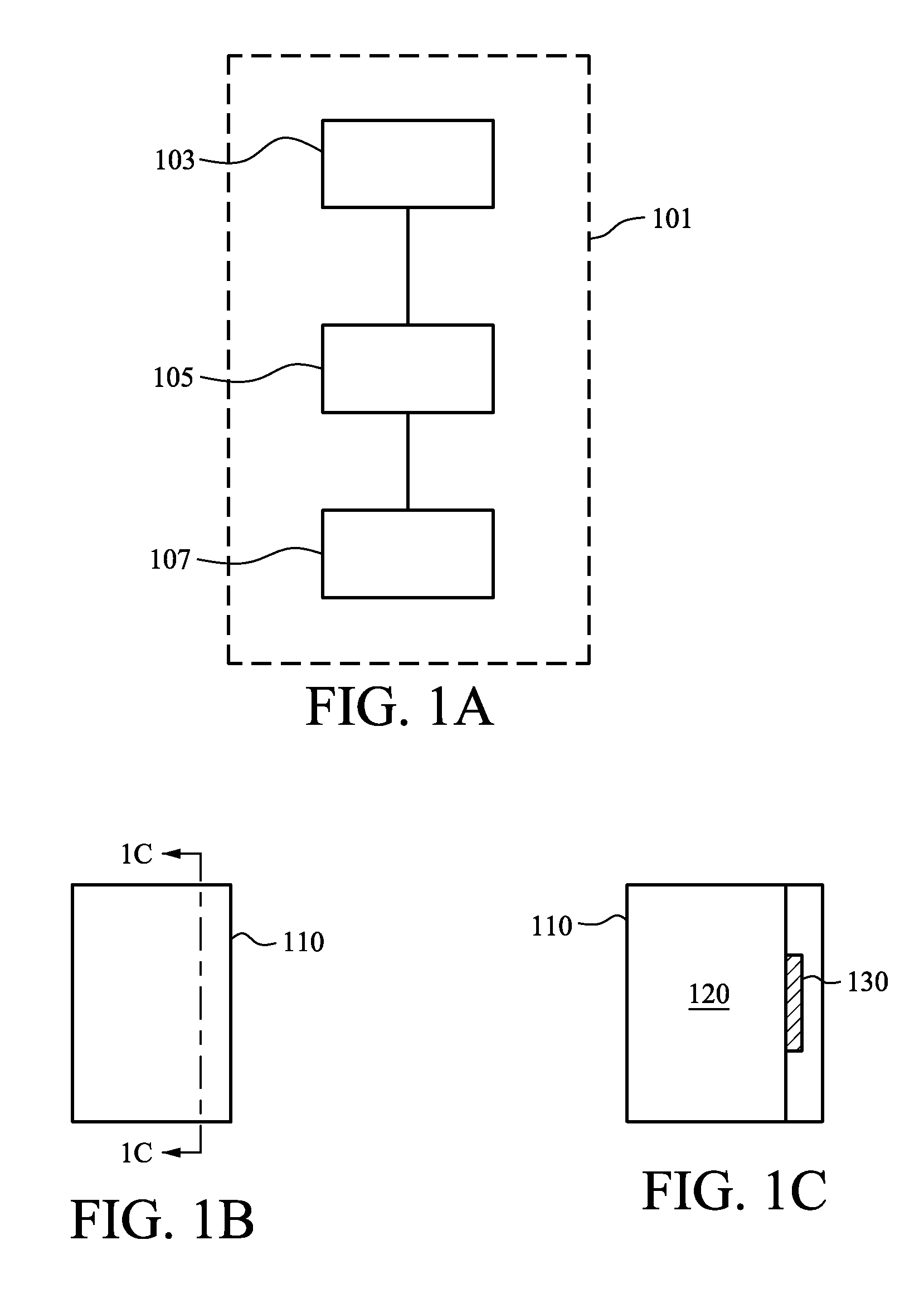
[0022]FIG. 1A shows a block diagram of a defrost heater 101, which can be used for example in a household refrigeration appliance 110 (FIGS. 1B and 1C). The defrost heater 101 comprises a defrost heater 103, a control facility 105 and a temperature sensor 107. The temperature sensor 107 is provided to detect the actual defrost temperature and forward this to the control facility 105. The control facility 105 controls the defrost heater 103 according to a predetermined defrost temperature profile so that the predetermined defrost temperature profile is established over time at the temperature sensor. Referring to FIG. 1B, a refrigeration appliance 100 is shown. As can be seen in FIG. 1C, the refrigeration appliance includes a chamber to be cooled 120 and an evaporator (e.g., a finned evaporator 130) disposed outside the chamber to be cooled.

[0023]FIG. 2 illustrates an example of a defrost temperature profile with a linear, ramped intermediate defrost temperature segment 201, which co...


PUM


Abstract

A refrigeration appliance includes an evaporator and a defrost heater which periodically subjects the evaporator to a defrost process, A temperature sensor is disposed at least in proximity to the evaporator and is adapted for switching off the defrost heater once the temperature sensor detects a predetermined defrost temperature. The temperature sensor provides a predetermined defrost temperature profile having first, second and third time segments. A first defrost temperature during the first time segment changes to a second defrost temperature during the second time segment, and holds the second defrost temperature during the third time segment.

Description

BACKGROUND OF THE INVENTION[0001]The present invention relates to the field of refrigeration appliances, in particular the field of household refrigeration appliances.[0002]Modern household refrigeration appliances have defrost heaters, which are provided to thaw unwanted frost and ice. In this process a defrost period is controlled by a temperature sensor positioned for example on the evaporator of the refrigeration appliance, said temperature sensor detecting a predefined final defrost temperature, on the reaching of which the defrost heater is switched off or remains switched on for a further minimum defrost time, it only being possible to switch the defrost heater off within the minimum defrost time, if a safety temperature threshold is exceeded.[0003]However if the preset final defrost temperature is reached too quickly, the heat emitted by the defrost heater cannot be distributed evenly in the evaporator. This means that the unwanted ice is not thawed at a point further away f...

Claims


Application Information

Patent Timeline
Patent Type & Authority Patents(United States)
IPC IPC(8): F25D21/00F25D21/08
CPCF25D21/002F25D21/08F25D2700/10F25D29/00
Inventor FOTIADIS, PANAGIOTISHARLEN, JOCHENJOKSCH, HARALD
Owner BSH BOSCH & SIEMENS HAUSGERAETE GMBH
Learn More