
Refrigerator and control method thereof

a technology of refrigerator and control method, which is applied in the direction of domestic refrigerator, defrosting, domestic cooling apparatus, etc., can solve the problems of consuming a large amount of power as compared with the cord heater, reducing the efficiency of defrosting, and reducing the power consumption of the defrosting process. , to achieve the effect of efficient defrosting and reducing the power consumption

Active Publication Date: 2020-06-04
SAMSUNG ELECTRONICS CO LTD
View PDF7 Cites 3 Cited by
  • Summary
  • Abstract
  • Description
  • Claims
  • Application Information

AI Technical Summary

Benefits of technology

The patent is about a refrigerator and how it can efficiently defrost itself using a sheath heater. This helps to save power because the refrigerator doesn't have to use as much electricity to defrost itself. The patent describes a method for dividing the evaporator into sections and focusing on defrosting those sections first, which results in better efficiency and reduced power consumption during the defrosting process.

Problems solved by technology

Furthermore, heat resistance on the surface of the evaporator increases and as a result, performance of the refrigeration cycle is degraded.
The cord heater is inexpensive but has a weak point in that it still leaves a large amount of frost after the defrost process.
The sheath heater leaves less frost than the cord heater, but consumes a large amount of power as compared with the cord heater.
It is common for the recent refrigerator to use both the aforementioned cord heater and sheath heater to increase energy efficiency, however the combination also significantly increases the cost of operating the refrigerator.
This may cause an inefficient situation where some portions of the evaporator are overheated more than necessary.

Method used


Image

  • Refrigerator and control method thereof
  • Refrigerator and control method thereof
  • Refrigerator and control method thereof

Examples


Embodiment Construction

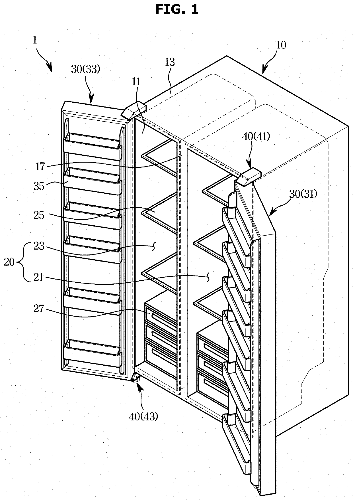
[0055]FIGS. 1 through 16, discussed below, and the various embodiments used to describe the principles of the present disclosure in this patent document are by way of illustration only and should not be construed in any way to limit the scope of the disclosure. Those skilled in the art will understand that the principles of the present disclosure may be implemented in any suitably arranged system or device.

[0056]Like numerals refer to like elements throughout the specification. Not all elements of embodiments of the disclosure will be described, and description of what are commonly known in the art or what overlap each other in the embodiments will be omitted. The term ‘unit, module, member, or block’ may refer to what is implemented in software or hardware, and a plurality of units, modules, members, or blocks may be integrated in one component or the unit, module, member, or block may include a plurality of components, depending on the embodiment of the disclosure.

[0057]It will be...


PUM


Abstract

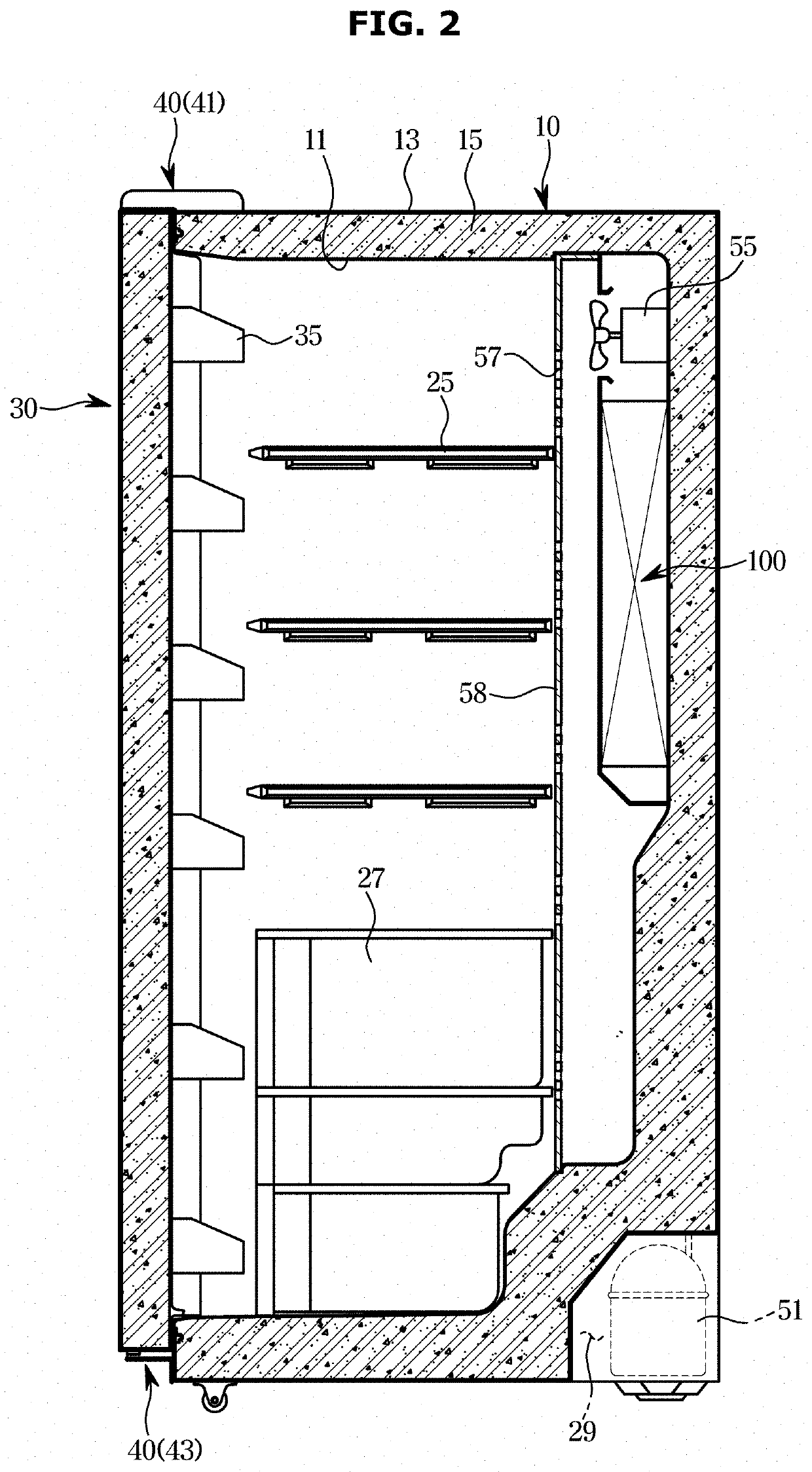
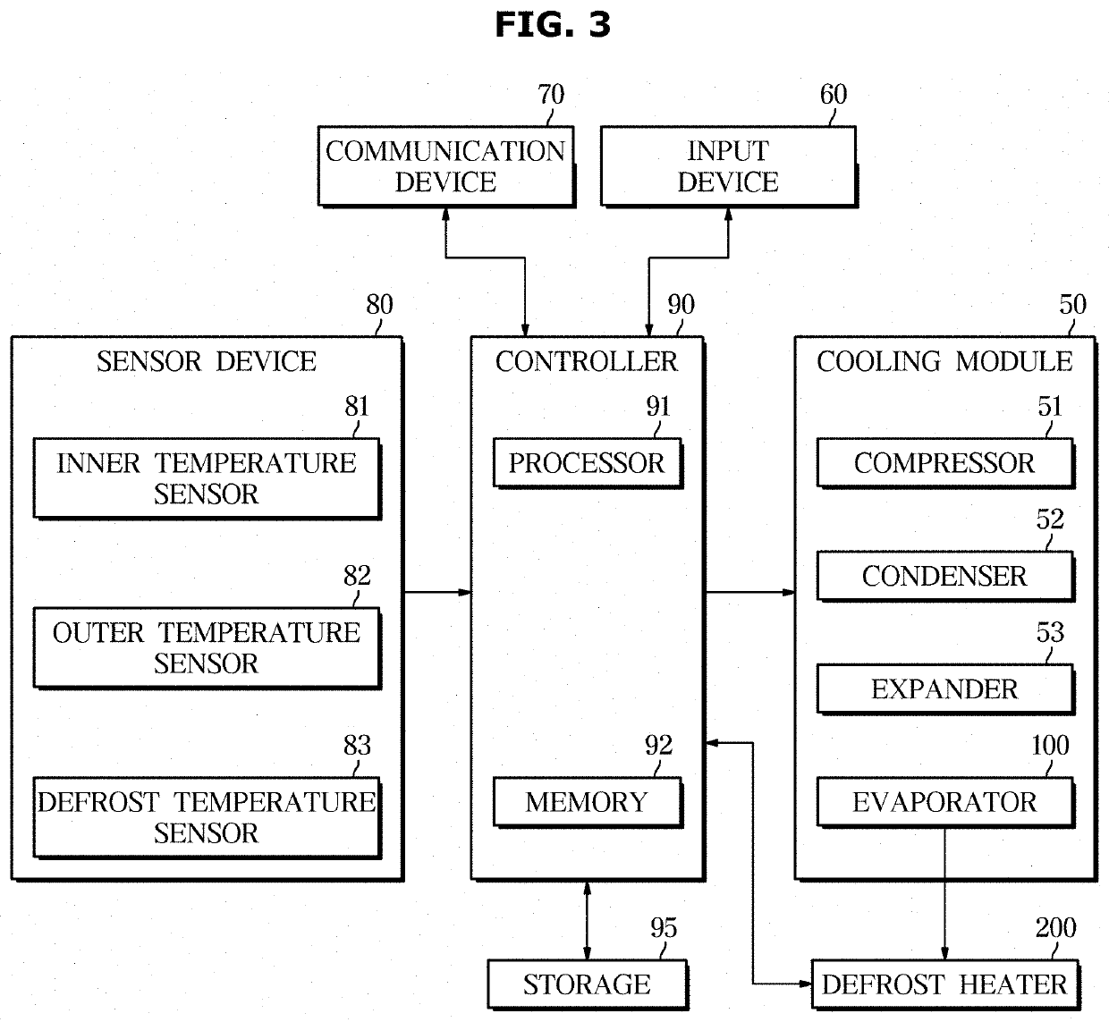
A refrigerator including a main body including a storeroom; an evaporator arranged in the back of the storeroom and configured to generate cold air; a defrost heater arranged under the evaporator into which air flows and configured to remove frost or ice formed on the evaporator; a temperature sensor arranged on the top of the evaporator and configured to measure temperature; and a controller configured to stop operation of the defrost heater in a first defrost cycle based on a first measurement measured by the temperature sensor and stop operation of the defrost heater in a second defrost cycle based on a second measurement, which is different from the first measurement.

Description

CROSS-REFERENCE TO RELATED APPLICATION[0001]This application is based on and claims priority under 35 U. S. C. § 119 to Korean Patent Application No. 10-2018-0149880 filed on Nov. 28, 2018, the disclosure of which is incorporated herein by reference in its entirety.BACKGROUND1. Field[0002]The disclosure relates to a refrigerator and control method thereof for efficiently removing frost or ice formed on an evaporator.2. Discussion of Related Art[0003]Refrigerators are devices having a storeroom and a cold air supply for supplying cold air into the storeroom to keep food fresh.[0004]The storeroom has an open front, which is closed by a door at ordinary times to maintain a temperature of the storeroom.[0005]The cold air supply keeps the storeroom at a low temperature by pumping heat out of the storeroom by using a vapor compression refrigeration cycle.[0006]The cold air supply includes an evaporator for generating cold air, a blower fan for guiding the cold air generated by the evapora...

Claims


Application Information

Patent Timeline
Patent Type & Authority Applications(United States)
IPC IPC(8): F25D21/00F25D21/08F25D11/02
CPCF25D21/006F25D2600/02F25D11/02F25D21/08F25D21/004F25D21/008F28D15/0275F25D2700/10F25D2600/06
Inventor KIM, MIN SOOJEONG, HEE MOONSEO, KOOK JEONG
Owner SAMSUNG ELECTRONICS CO LTD
Learn More