Heat-pump-type vehicle air conditioning system and defrosting method thereof

a vehicle air conditioning system and heat pump technology, applied in refrigeration components, lighting and heating apparatus, transportation and packaging, etc., can solve the problems of reducing cabin heating performance, reducing the quantity of heat absorbed from external air, and electric vehicles (ev) cannot use engine waste heat for cabin heating, etc., to achieve efficient defrosting in a short period of time, simple configuration, and low cost

Inactive Publication Date: 2018-08-07
MITSUBISHI HEAVY IND THERMAL SYST
View PDF16 Cites 3 Cited by
  • Summary
  • Abstract
  • Description
  • Claims
  • Application Information

AI Technical Summary

Benefits of technology

[0024]According to the heat-pump-type vehicle air conditioning device of the present invention, the vehicle-cabin-exterior condenser and the vehicle-cabin-exterior vaporizer can be efficiently defrosted in a short period of time even under low outside air temperature conditions by introducing hot gas refrigerant output from the electric compressor to the vehicle-cabin-exterior condenser and the vehicle-cabin-exterior vaporizer via the first defrosting circuit and the second defrosting circuit respectively, when the vehicle-cabin-exterior vaporizer is frosted or snow or ice or the like is adhering to the vehicle-cabin-exterior condenser as a result of cabin heating operation during low outside temperature conditions. Moreover, virtually all the refrigerant circuit of current air conditioning systems can be used as they are. Therefore, by adding the minimum cabin heating circuit and equipment, the highly reliable and high-efficiency heat-pump-type vehicle air conditioning system with the comparatively simple configuration, low cost, excellent mountability, and that can be ideally adopted for EV vehicles, HEV, and PHEV vehicles and the like can be provided.
[0025]According to the defrosting method of the heat-pump-type vehicle air conditioning device of the present invention, during defrosting operation, after the snow or frozen water that has been sprayed up and is adhering to the vehicle-cabin-exterior condenser has been defrosted by the first defrosting circuit using the hot gas refrigerant, the circuit is switched to the second defrosting circuit, and the frosting of the vehicle-cabin-exterior vaporizer is defrosted by the hot gas refrigerant. Therefore, hot gas refrigerant is fed in a concentrated manner separately to the vehicle-cabin-exterior condenser and the vehicle-cabin-exterior vaporizer, so they can be efficiently defrosted in a short period of time even under low outside air temperature conditions.

Problems solved by technology

In vehicle air conditioning systems, electric vehicles (EV) cannot use the waste heat of the engine for cabin heating.
On the other hand, in the case of heat pump systems, when operating cabin heating under low outside air temperature conditions, frosting can occur on the vehicle-cabin-exterior heat exchanger (evaporator), resulting in a reduction in the quantity of heat absorbed from the external air, which has the problem that the cabin heating performance is reduced.
Therefore, it is necessary to defrost the vehicle-cabin-exterior heat exchanger (evaporator), but if a defrosting system adapted for building heat pump air conditioning apparatus is adopted, cabin heating operation cannot be continued.
In the case of a vehicle air conditioning device, if the cabin heating operation is stopped, the windows become fogged and safety cannot be ensured, so there is a problem that it is difficult to carry out defrosting operation while driving.

Method used


Image

  • Heat-pump-type vehicle air conditioning system and defrosting method thereof
  • Heat-pump-type vehicle air conditioning system and defrosting method thereof
  • Heat-pump-type vehicle air conditioning system and defrosting method thereof

Examples


Embodiment Construction

[0041]An embodiment of the present invention will be described below with reference to FIGS. 1 to 13.

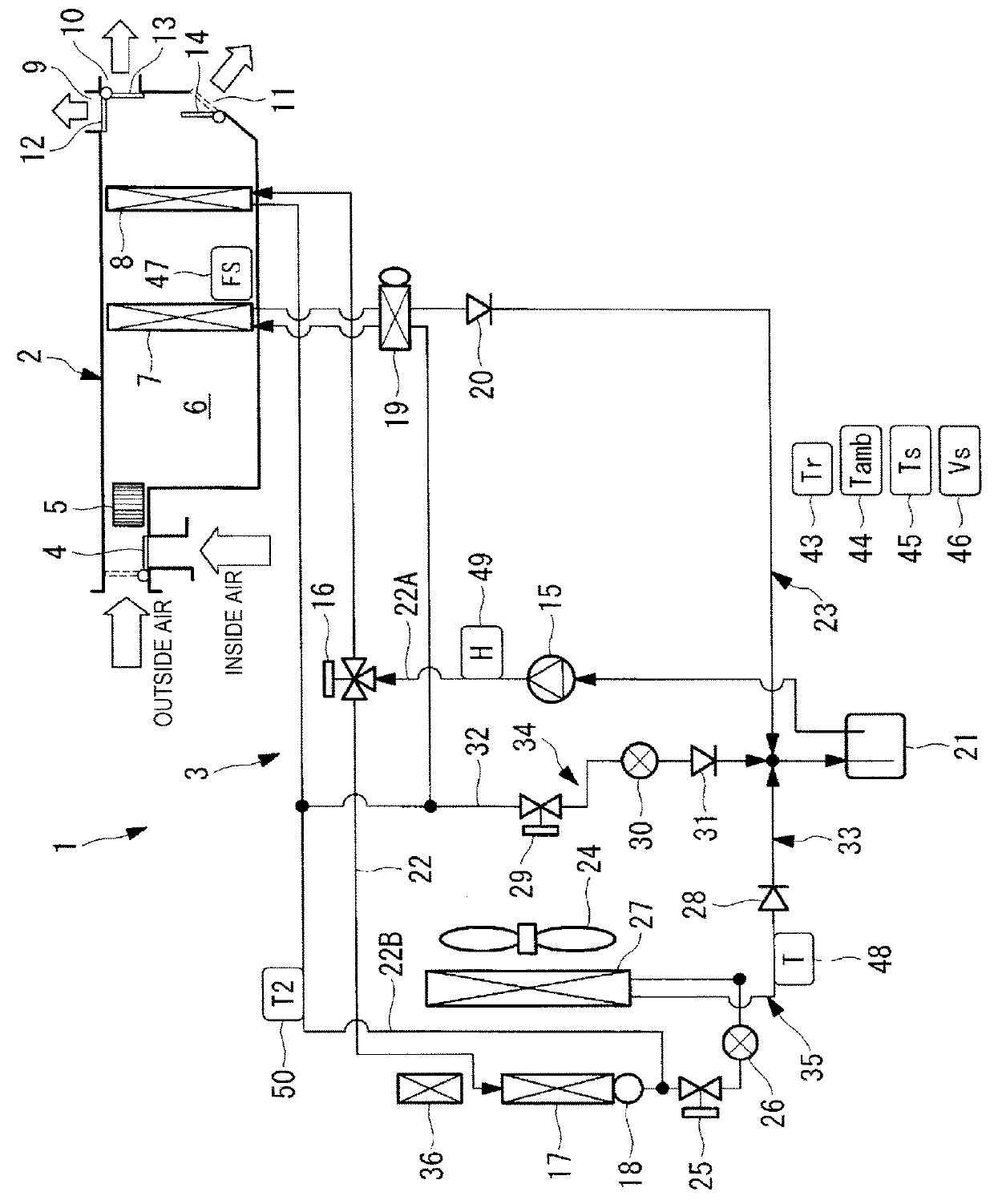
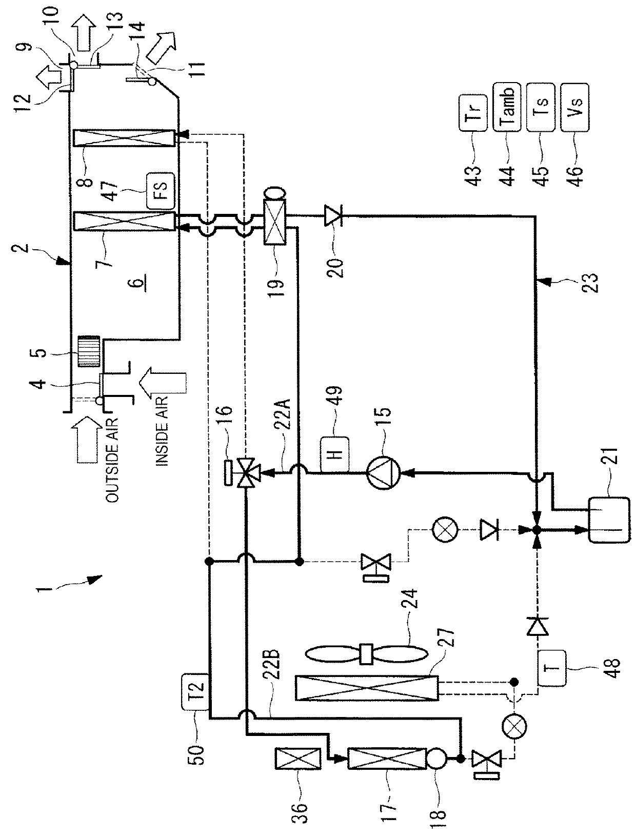
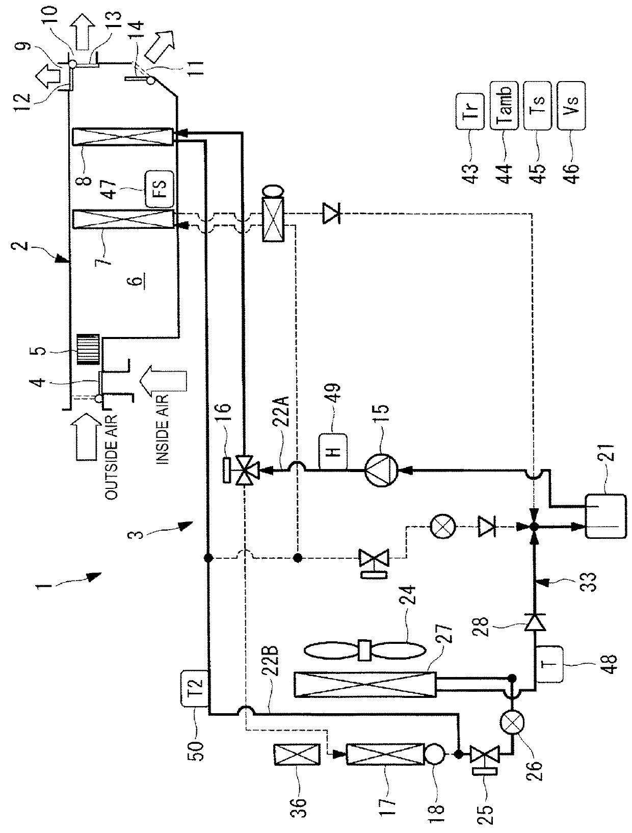
[0042]FIG. 1 is a refrigerant circuit diagram of a heat-pump-type vehicle air conditioning system according to an embodiment of the present invention.

[0043]A heat-pump-type vehicle air conditioning system 1 according to the present embodiment includes a heating ventilation and air conditioning unit (HVAC unit) 2, and a heat pump cycle 3 capable of heating and cooling.

[0044]The HVAC unit 2 includes a blower 5 that can switch introduction of inside air from within the vehicle cabin or outside air using an inside and outside air switching damper 4 that switches between inside and outside air, and delivers the air under pressure to the downstream side, and a vehicle-cabin-interior vaporizer 7 and a vehicle-cabin-interior condenser 8 disposed in that order from the upstream side to the downstream side of an air flow channel 6 that is connected with the blower 5. The HVAC unit 2 is dispose...


PUM


Abstract

A heat pump vehicle air conditioning system passes hot gas to a condenser and a vaporizer for the vehicle cabin exterior. Even with low outside air temperature, it can efficiently defrost using the cooling cycle. The system includes a cabin-interior condenser downstream of a cabin-interior vaporizer within an HVAC unit connected via refrigerant switching means to a cooling cycle. Cooling is accomplished by a compressor, cabin-exterior condenser, first decompression unit with on-off valve function, the cabin-interior vaporizer, and an accumulator. A cabin-exterior vaporizer disposed outside of the vehicle cabin is connected with a second decompression unit via an on-off valve function and to the exit-side liquid refrigerant pipe of the cabin-exterior condenser. A bypass circuit having a third decompression unit with on-off function is connected between the accumulator and the exit-side liquid refrigerant pipe of the cabin-exterior condenser.

Description

TECHNICAL FIELD[0001]The present invention relates to a heat-pump-type vehicle air conditioning system and a defrosting method thereof that can be applied to the air conditioning device of an electric vehicle, hybrid vehicle, or the like.BACKGROUND ART[0002]In vehicle air conditioning systems, electric vehicles (EV) cannot use the waste heat of the engine for cabin heating. In hybrid vehicles (HEV, PHEV) also, engines are controlled to be stopped as much as possible for fuel economy, so the adoption of heat pump cabin heating systems using a refrigerant and heating systems using an electric heater with coolant as a medium is being investigated. In particular, for cabin heating operation, the power consumption is large, so it is desirable to use a heat pump system that can achieve high COP cabin heating (in the case of an electric heater, COP≤1).[0003]On the other hand, in the case of heat pump systems, when operating cabin heating under low outside air temperature conditions, frosti...

Claims


Application Information

Patent Timeline
Patent Type & Authority Patents(United States)
IPC IPC(8): B60H1/32B60H1/22B60H1/00F25B41/04F25B47/02
CPCB60H1/22B60H1/00778B60H1/00785B60H1/00899F25B41/04F25B47/022B60H1/00921F25B2400/0411F25B2341/0683F25B2400/0409B60H2001/00961F25B41/20F25B41/24
Inventor MORISHITA, MASATOSHIISHIDA, TOSHIYUKI
Owner MITSUBISHI HEAVY IND THERMAL SYST
Why Eureka
Try Eureka