Alarm sound detection device

an alarm sound and detection device technology, applied in the direction of electric signalling details, instruments, television systems, etc., can solve the problems of erroneous detection of alarm sounds, disappearance of alarm sounds, and difficulty for store staff to identify

Active Publication Date: 2017-01-03
I & T TECH
View PDF10 Cites 2 Cited by
  • Summary
  • Abstract
  • Description
  • Claims
  • Application Information

AI Technical Summary

Benefits of technology

[0025]According to this invention, an abnormality detection device can be realized, in which a false detection almost does not occur, an alarm sound detection from weak alarm sound becomes possible. And according to this invention, such security information as shoplifting, fire, customer's position at the store, and the position where customer calls store staff can be accessible.And then based on this security information, it becomes possible to control CCTV camera system and monitor the store situation in detail by CCTV images and to constitute the integrated security system.

Problems solved by technology

When tag emits the alarm sound at the store with background music or with noise sound or at the wide floor space store and with few store staff, sometimes its alarm sound is erroneously detected or it was difficult for store staff to identify the alarm position and / or the shoplifter.
In addition, when tag which emit its alarm sound, is destroyed and / or is put into the water pod, its alarm sound will disappear in a short time or it is also very difficult to detect this alarm.
But this type of antenna was rather big as 1 m H*40 cm W and its price also rather expensive.
So it was difficult to place the receiving antennas at several places in the store and increase the security level.
In some cases, if this type of big antenna would be installed in the high end brand store entrance, the antenna existence, itself, might damage the esthetic entrance image, and so EAS antenna would be buried under the floor.
And in this under-the-floor antenna case, the antenna would receive more nearby electro-magnetic noise from under-the-floor power line and its performance would become more instable and poor.
But by the store background music, customer's voice, outside noise and furthermore by the echo sound from such wall and / or ceiling as the construction object, the alarm sound may be affected and its alarm sound becomes fairly different from the original alarm sound and then reliable detection of the alarm sound seemed to be difficult and so far, sound detection method of the alarm was not used in the security field.

Method used


Image

  • Alarm sound detection device
  • Alarm sound detection device
  • Alarm sound detection device

Examples


first embodiment

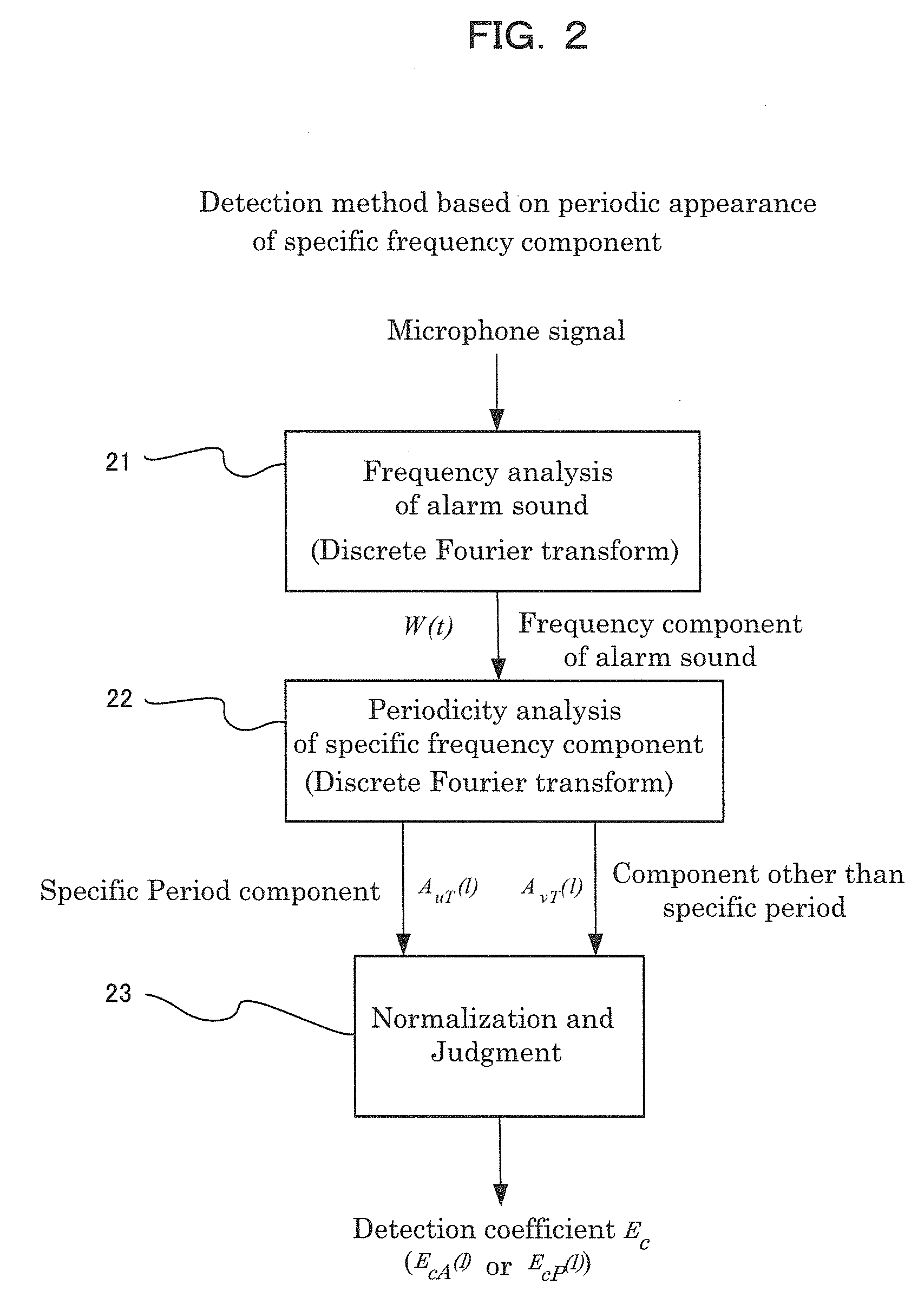
[0046]As this invention, FIG. 2 shows the alarm sound detection method based on the periodic appearance of the specific frequency component. Firstly the specific frequency component of the alarm sound is detected by the frequency analyzer 21. In this case, frequency amplitude and / or power component are calculated sequentially by such a frequency analysis as discrete Fourier transform analysis at the several period (for ex. 4-32 periods) of the alarm sound.

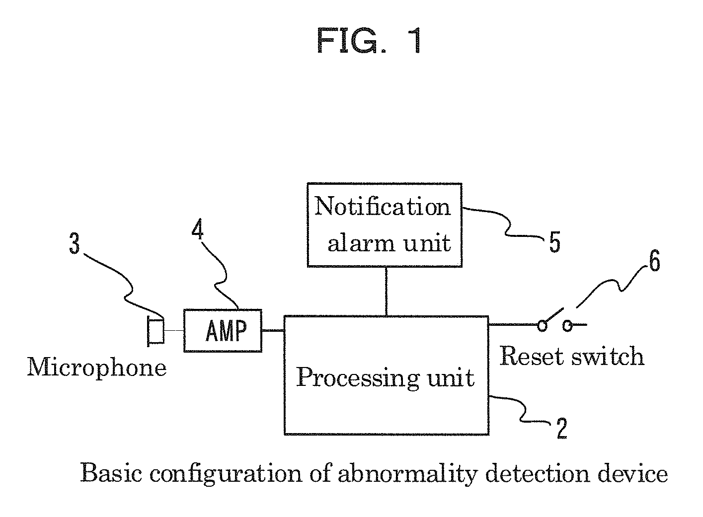
[0047]This analysis process method can be shown as follows by the discrete Fourier transform analysis. Sound signal including target alarm sound detected at microphone 3 can be digitally input into processing unit 2 through microphone amplifier 4. At this time, sound signal is sampled at the sampling frequency k·f(k>2), k—times of the specific frequency f included in the target alarm sound.

[0048]Digital signal sampled at the n th order is denoted as St(n). Discrete Fourier transform Sf(f) of detected alarm sound sampled at the dura...

third embodiment

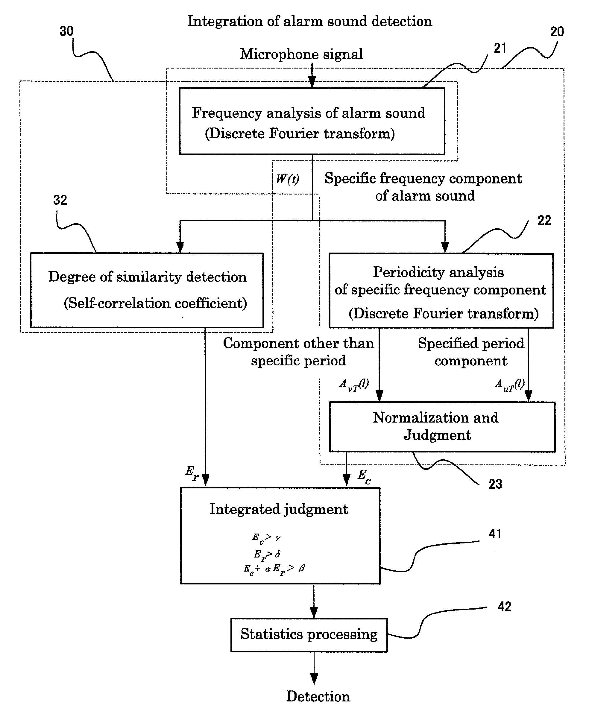
[0083]FIG. 5 shows this invention. That is at the process block 20 surrounded with dotted line, firstly a specific frequency component W(t) of the alarm sound is calculated by the frequency analyzer 21.

[0084]Secondly further frequency analysis by the period analyzer 22, using the same Fourier transform etc., at the time domain change waveform of an amplitude component A(f) or a power component P(f) of the specific frequency component calculates the repeatedly-appearing period component of specific frequency component AuT(l).

[0085]At this time, period component AvT(l) other than the repeatedly appearing period component of specific frequency component, is also calculated, and by the normalization that AuT(l) is divided by AvT(l) and the judgment part 23, the detection coefficient Ec is calculated.

[0086]Further this process 20 which calculates detection coefficient Ec is the same method as the period analyzer of a specific frequency component, as shown in FIG. 2 as the first embodimen...

second embodiment

[0088]Further this process 30 which calculates the detection coefficient is the same method as the similarity detector of time domain change waveform of a specific frequency component, shown in FIG. 4 as this invention.

[0089]Further in FIG. 5, frequency analyzer 21 is used both in the first embodiment of this invention and second embodiment of this invention and is commonly used and shown in this figure, but frequency analyzer 21 can be used separately.

[0090]Total judgment part 41 detects the alarm sound by the relationship inequality of 2 detection coefficients Ec and Er.

[0091]As an example, the case in which simple 1st order relationship inequalities are used, is shown in the following. That is, in this example, when following 3 conditions are met, alarm sound detection is judged.

Ec>γ  [Equation 12]

Er>δ  [Equation 13]

Ec+αEr>β  [Equation 14]

[0092]Herein the values α, β, γ, δ shown in aforesaid inequalities can be decided by experiment, when there is no alarm sound, on the condition...


PUM


Abstract

By detecting the specific frequency component included in an alarm sound by a frequency analysis and a period analysis, even under a noisy and echo environment, a reliable, almost-no-false-detecting and small-sized abnormality detection device, which can detect the alarm sound, can be realized and then an integrated security system can be realized.

Description

FIELD OF THE INVENTION[0001]This invention is related to an anti-theft, abnormality detection device and its security system.BACKGROUND OF THE INVENTION[0002]Anti-theft self-alarming tags, which have been widely known in the store security field, include micro-processor like micro-computer, abnormality state detection circuit and buzzer alarm circuit etc inside the tag. In an emergency, tag emits the alarm sound which makes people feel uncomfortable, and makes people know the occurrence of abnormality state.[0003]Abnormality state which emits the alarm sound, defines such a state as the said self-alarming tag is removed from the merchandise and / or as the self-alarming tag receives the signal from transmission antenna of EAS (Electro-Article Surveillance) antenna which is installed at the store entrance.[0004]As its alarm sound, the intermittent type alarm sound whose alarm sound frequency is several kHz and alarm sound repetition cycle is few cycle / second, or the swept frequency typ...

Claims


Application Information

Patent Timeline
Patent Type & Authority Patents(United States)
IPC IPC(8): G08B1/08G08B1/00G08B3/10H04N7/18G08B1/02
CPCG08B1/08G08B1/00G08B3/10H04N7/188G08B1/02
Inventor ASADA, KATSUHIKO
Owner I & T TECH
Why Eureka
Try Eureka