Optical information recording apparatus

US20050265184A1Inactive Publication Date: 2005-12-01TAIYO YUDEN KK

Image

  • Optical information recording apparatus
  • Optical information recording apparatus
  • Optical information recording apparatus

Examples


Embodiment Construction

[0068] Hereinafter, an optical information recording apparatus according to the present invention will be described in detail with reference to the accompanying drawings. It is, however, to be noted that the present invention is not limited to the following embodiments, but can be changed in a variety of ways.

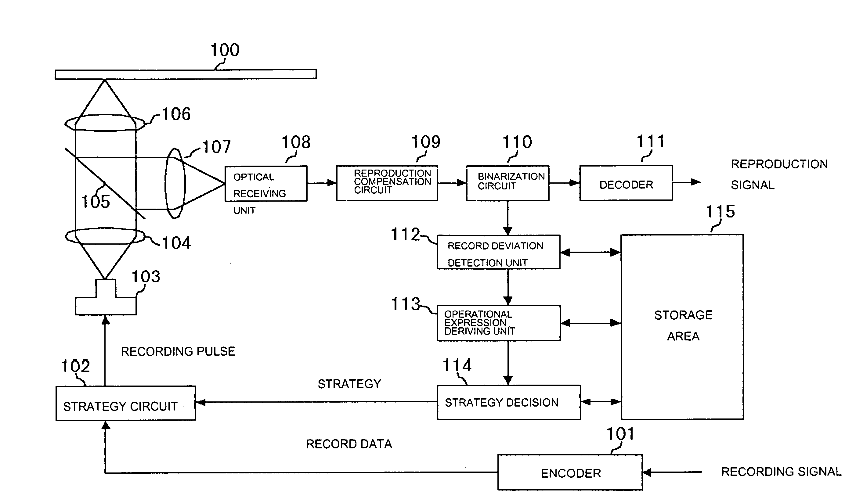
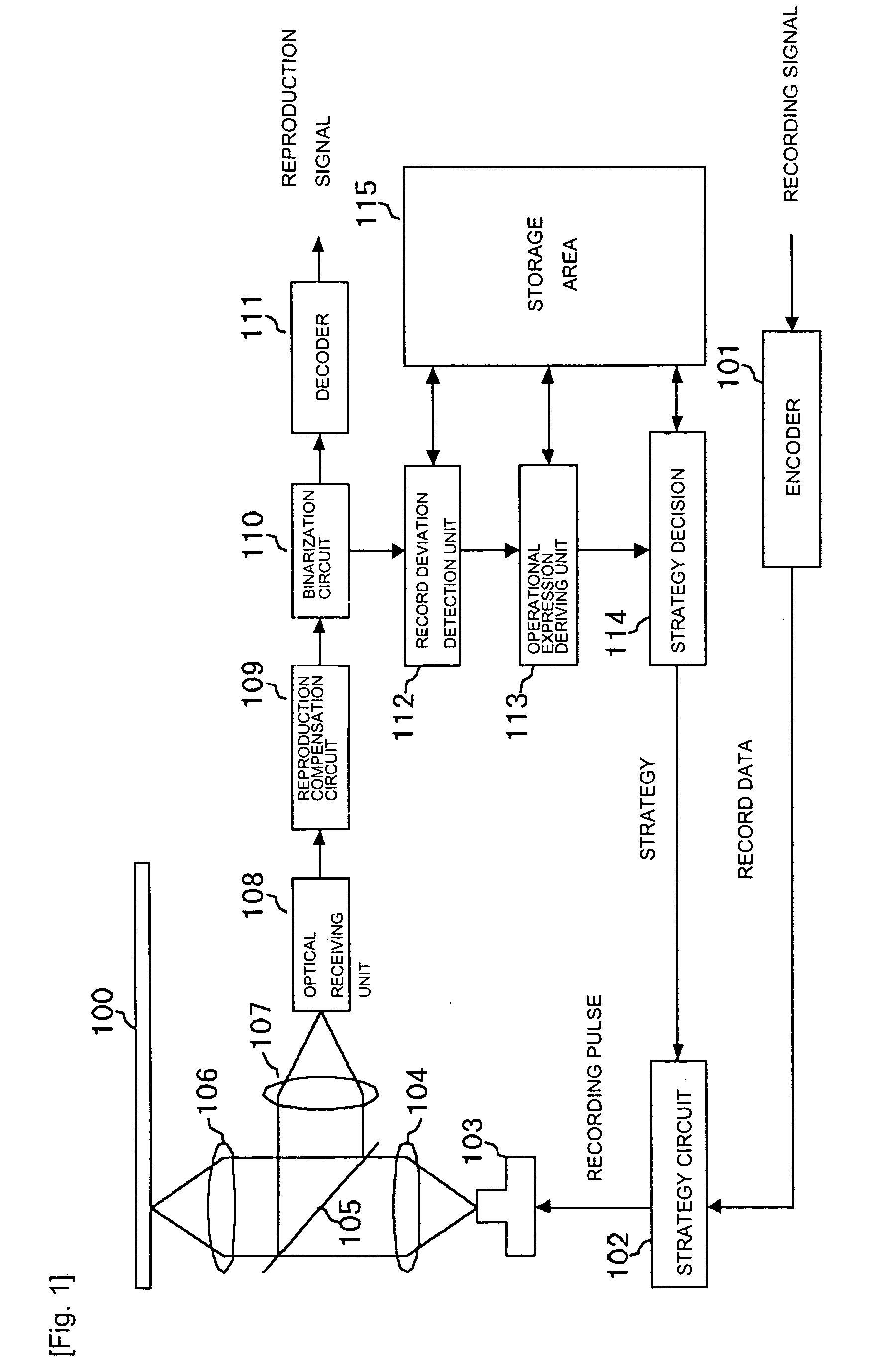
[0069]FIG. 1 is a block diagram showing an internal construction of an optical information recording apparatus according to the present invention. As shown in FIG. 1, the optical information recording / reproducing device is adapted to record and reproduce information on and from an optical disk 100 using laser light output from a laser oscillator 103.

[0070] In the case where information is recorded on the optical disk 100, a recording signal corresponding to desired record information is encoded by means of an encoder 101 in the EFM mode, and the encoded record data are provided to a strategy circuit 102.

[0071] At this time, the strategy circuit 102 has various setting parame...


PUM


Abstract

An optical information recording apparatus is suitable for detection of deviation between a strategy and a record pattern. Test record is performed on an optical recordable medium using a predetermined strategy. A binarization signal that is obtained by reproducing the test record result is counted. A pit length and a land length included in the binarization signal are specified using a histogram of the count result. A plurality of the reproduction patterns is searched and extracted from a record area based at least in part on the pit length and the land length. Deviation between a strategy and a record pattern formed by the test record is detected through comparison of the obtained reproduction patterns through the search.

Description

BACKGROUND OF THE INVENTION 1. Field of the Invention [0001] The present invention relates to an optical information recording apparatus, and more particularly, to an optical information recording apparatus, which is effective in correcting phase deviation or length deviation of recording pits. 2. Description of the Related Art [0002] Recording information on an optical information record medium such as an optical disk is carried out in such a manner that record data are modulated in accordance with the EFM (Eight to Fourteen Modulation) mode, a recording pulse is formed according to the modulation signal, and recording pits are then formed on the optical disk through control of the intensity or irradiation timing of laser light based at least in part on the recording pulse. [0003] In this case, since the recording pits are formed using heat generating by irradiation of laser light, it is beneficial that the recording pulse be set by taking the effects of thermal storage, thermal in...

Claims


Application Information

Patent Timeline
01 Dec 2005
Publication
US20050265184A1
IPC
G11B5/09; G11B7/00; G11B7/0045; G11B7/125; G11B7/1267; G11B20/18
CPC
G11B7/00456; G11B7/1267; G11B7/00458; G11B7/004; G11B7/0045
Inventors
SEKIGUCHI, MITSUO; KAKIMOTO, HIROYA