Abnormality detection method, abnormality detection apparatus, and abnormality detection system

Active Publication Date: 2018-11-01
PANASONIC INTELLECTUAL PROPERTY CORP OF AMERICA
View PDF4 Cites 28 Cited by
  • Summary
  • Abstract
  • Description
  • Claims
  • Application Information

AI Technical Summary

Benefits of technology

[0010]According to the present disclosure, if an attack frame (message) is transmitted to a bus by an attacker, this can lead to a change such that the number of messages received within the unit time determined in the on-board network system is different from the criterion, and thus it is possible to detect an abnormality.

Problems solved by technology

There is a possibility that an attacker connects an invalid node to a CAN bus or attacks a portable information terminal or an ECU or the like having a capability of communicating with a communication apparatus outside a vehicle such that the attacked portable information terminal or the ECU is converted to an invalid node, and the attacker transmits an attack frame to the CAN bus to invalidly control the vehicle.
The techniques disclosed in Japanese Unexamined Patent Application Publication No. 2015-026252 and Japanese Unexamined Patent Application Publication No. 2015-170121 are not necessarily effective enough to detect an attack frame (that is, to detect an abnormality) on an on-board network, and thus there is a need for further research and development of techniques for detecting an abnormality.

Method used


Image

  • Abnormality detection method, abnormality detection apparatus, and abnormality detection system
  • Abnormality detection method, abnormality detection apparatus, and abnormality detection system
  • Abnormality detection method, abnormality detection apparatus, and abnormality detection system

Examples


first embodiment

[0058]An embodiment of the present disclosure is described below with reference to drawings for a case in which in an abnormality detection system, abnormality detection apparatus for detecting an abnormality in an on-board network in a vehicle is configured to determine, in cooperation with a server outside the vehicle, a detection window size (a unit time) used in detecting the abnormality. In this abnormality detection system, the abnormality detection apparatus sends, to a server, vehicle identification information on the vehicle in which the abnormality detection apparatus is installed, and determines the detection window size used in detecting an abnormality based on a response returned from the server.

1.1 Total Configuration of Abnormality Detection System 10

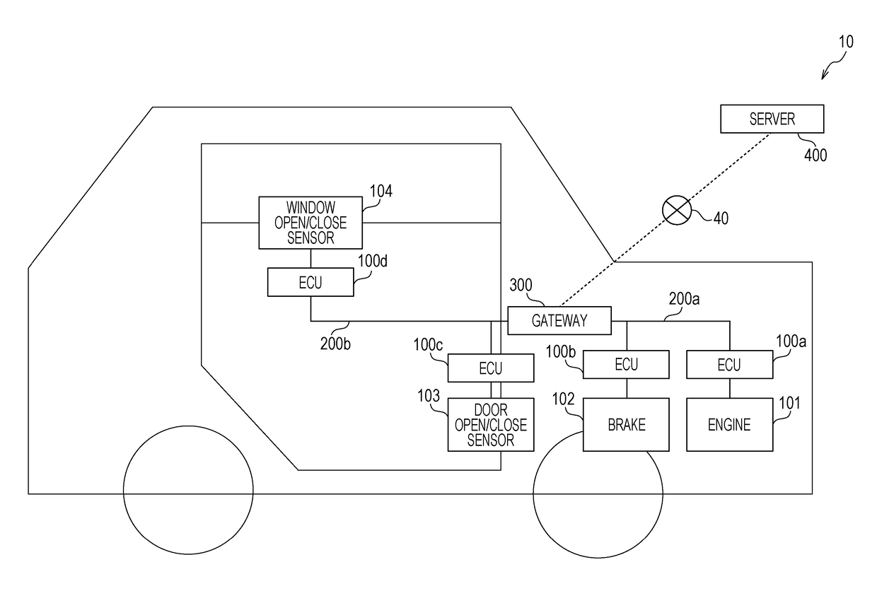
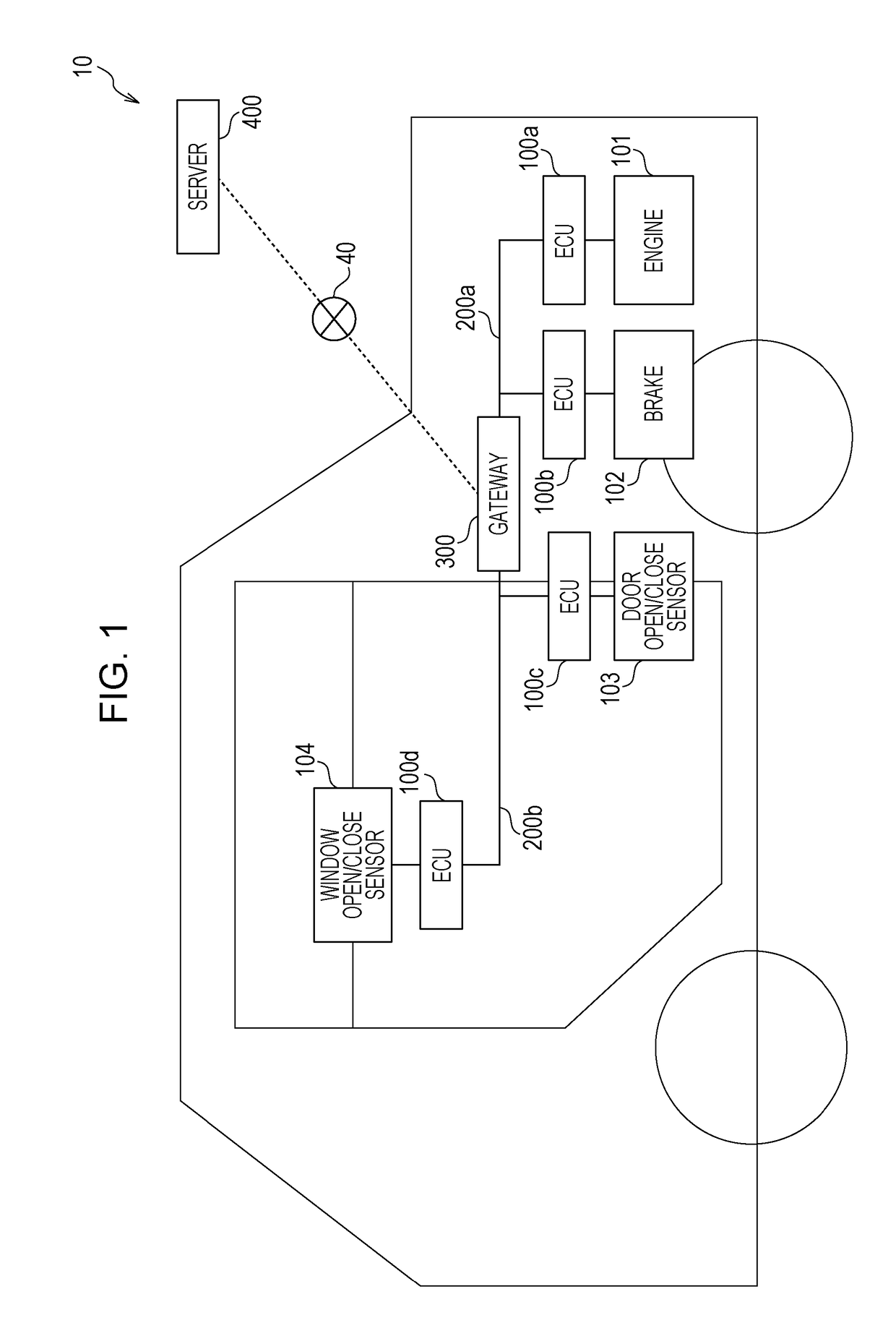
[0059]FIG. 1 is a diagram illustrating a total configuration of an abnormality detection system 10 according to a first embodiment.

[0060]The abnormality detection system 10 includes a vehicle including an on-board network...

second embodiment

[0149]A description is given below as an embodiment, which is a modification to the on-board network system of the vehicle in the abnormality detection system according to the first embodiment described above.

[0150]In the first embodiment, the detection window size is determined by the gateway 300 of the vehicle via the communication with the server 400 located outside the vehicle, and feature information based on the number of frames received in a time period corresponding to the detection window size counted individually for each ID is transmitted to the server 400 to allow it to update, via learning, the criterion model serving as the basis of the particular model used in detecting an abnormality in the on-board network. In contrast, in an example according to the second embodiment described below, a detection window size used in detecting an abnormality is determined independently by an abnormality detection apparatus of an on-board network system of a vehicle (that is, independ...


PUM


Abstract

An abnormality detection method is provided. The abnormality detection method is for detecting an abnormality that may be transmitted to a bus in an on-board network system. The on-board network system includes a plurality of electronic controllers that transmit and receive messages via the bus in a vehicle according to a CAN protocol. In the abnormality detection method, for example, a gateway transmits vehicle identification information to a server and receives a response determining a unit time. An operation process is performed using feature information based on a number of messages received from the bus per the determined unit time and using a model indicating a criterion in terms of a message occurrence frequency. A judgment is made as to an abnormality according to a result of the operation process.

Description

BACKGROUND1. Technical Field[0001]The present disclosure relates to a technique of detecting an abnormality in a message transmitted in an on-board network.2. Description of the Related Art[0002]In systems in vehicles according to recent techniques, many apparatuses called electronic control units (ECUs) are installed. A network via which those ECUs are connected is called an on-board network. There are many standards regarding on-board networks. Among those standards, one of the most major on-board network standards is the CAN (Controller Area Network) standard defined in ISO11898-1.[0003]In CAN, a bus (a CAN bus) including two wires is used as a communication channel, and ECUs connected to the bus are called nodes. Each node connected to the CAN bus transmits and receives a frame (a message).[0004]Furthermore, in CAN, no identifier exists to indicate a transmission destination or a transmission source. A transmission node transmits frames each of which is attached with an ID calle...

Claims


Application Information

Patent Timeline
Patent Type & Authority Applications(United States)
IPC IPC(8): H04L12/26H04L12/40
CPCH04L43/0823H04L12/40H04L2012/40273H04L2012/40215H04W4/48G06F21/85H04L63/1408H04L41/145H04W12/61H04L63/1416
Inventor UJIIE, YOSHIHIROHAGA, TOMOYUKIMAEDA, MANABUMATSUSHIMA, HIDEKIKISHIKAWA, TAKESHITSURUMI, JUNICHIKASHIMA, HISASHITORIUMI, YUKINOKUWAHARA, TAKUYA
Owner PANASONIC INTELLECTUAL PROPERTY CORP OF AMERICA
Why Eureka
Try Eureka