Method for Detecting an Optical Structure

a technology of optical structure and detection method, applied in the field of optical structure detection, can solve the problems of difficult to detect body structures using image recording systems, difficult to implement this method for image objects without distinct edges, and inability to calibrate based on edges

Active Publication Date: 2007-12-27
ROBERT BOSCH GMBH
View PDF3 Cites 22 Cited by
  • Summary
  • Abstract
  • Description
  • Claims
  • Application Information

AI Technical Summary

Benefits of technology

[0007] An example embodiment of the present invention may avoid these disadvantages and may make it possible to detect optical structures such as, in particular, edges on vehicle components such as, in particular, the hood of the vehicle, even under difficult optical conditions. The detected optical structures are advantageous for calibrating an image recording system using onboard devices even in vehicles having a modern vehicle design and in the case of strongly reflective surfaces. Furthermore, an example method according to the present invention may be advantageous for detecting the roll angle or the roll rate of a vehicle.
[0008] In accordance with the present invention, the derivation of an optical flow field from image sequences detected by an image recording system and projection of the flow vectors of the optical flow field onto a coordinate system make it possible to detect a change of direction of components of the flow vectors of the flow field. Image elements that contain such a change of direction may be connected to form a curve that represents the optical structure.

Problems solved by technology

Modern body shapes, however, pose considerable practical problems because present-day hoods frequently no longer have distinct edges, so that calibration based on edges is no longer possible.
Furthermore, high-gloss paints commonly used today result in mirror effects that make it difficult to detect body structures using an image recording system.
However, it is difficult to implement this method for image objects without distinct edges and with strongly reflective surfaces on image objects.

Method used


Image

  • Method for Detecting an Optical Structure
  • Method for Detecting an Optical Structure
  • Method for Detecting an Optical Structure

Examples


Embodiment Construction

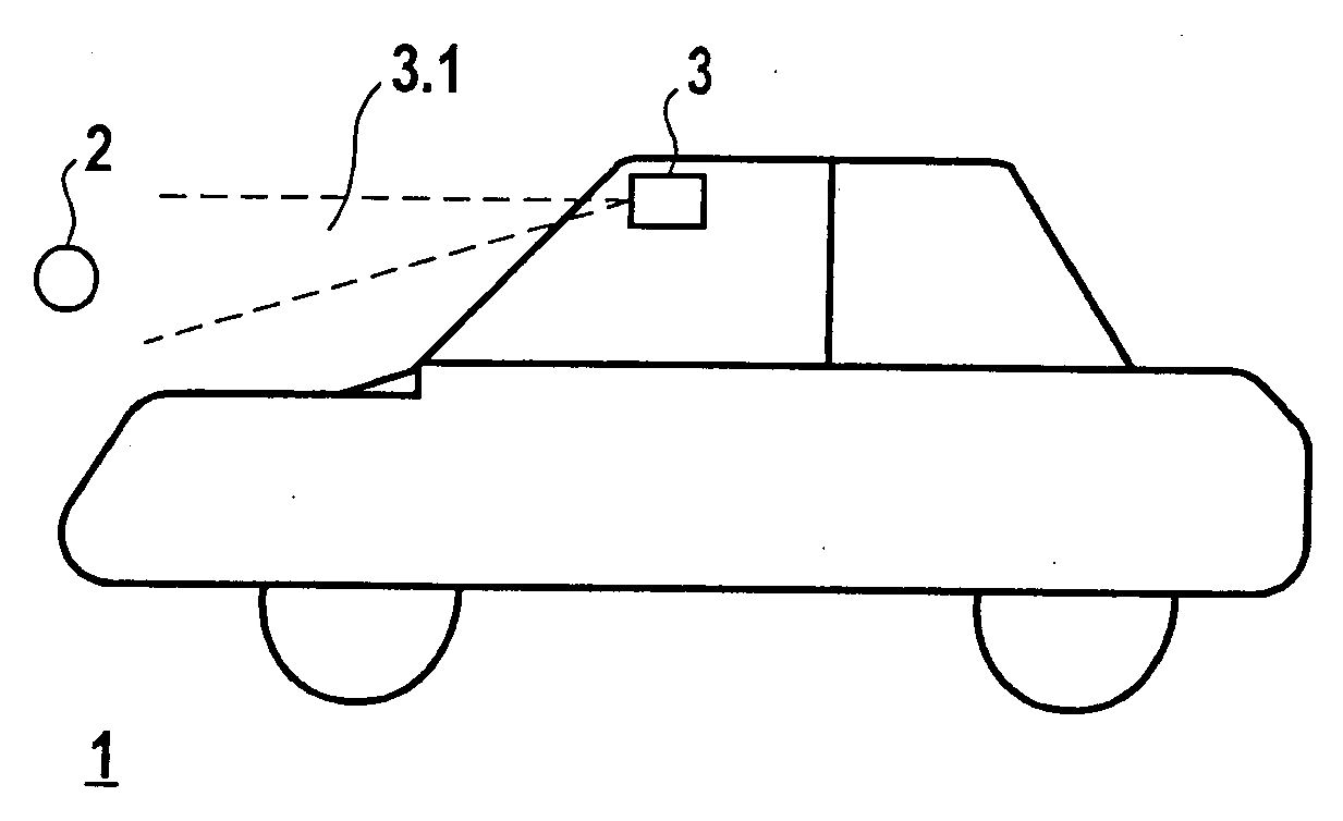
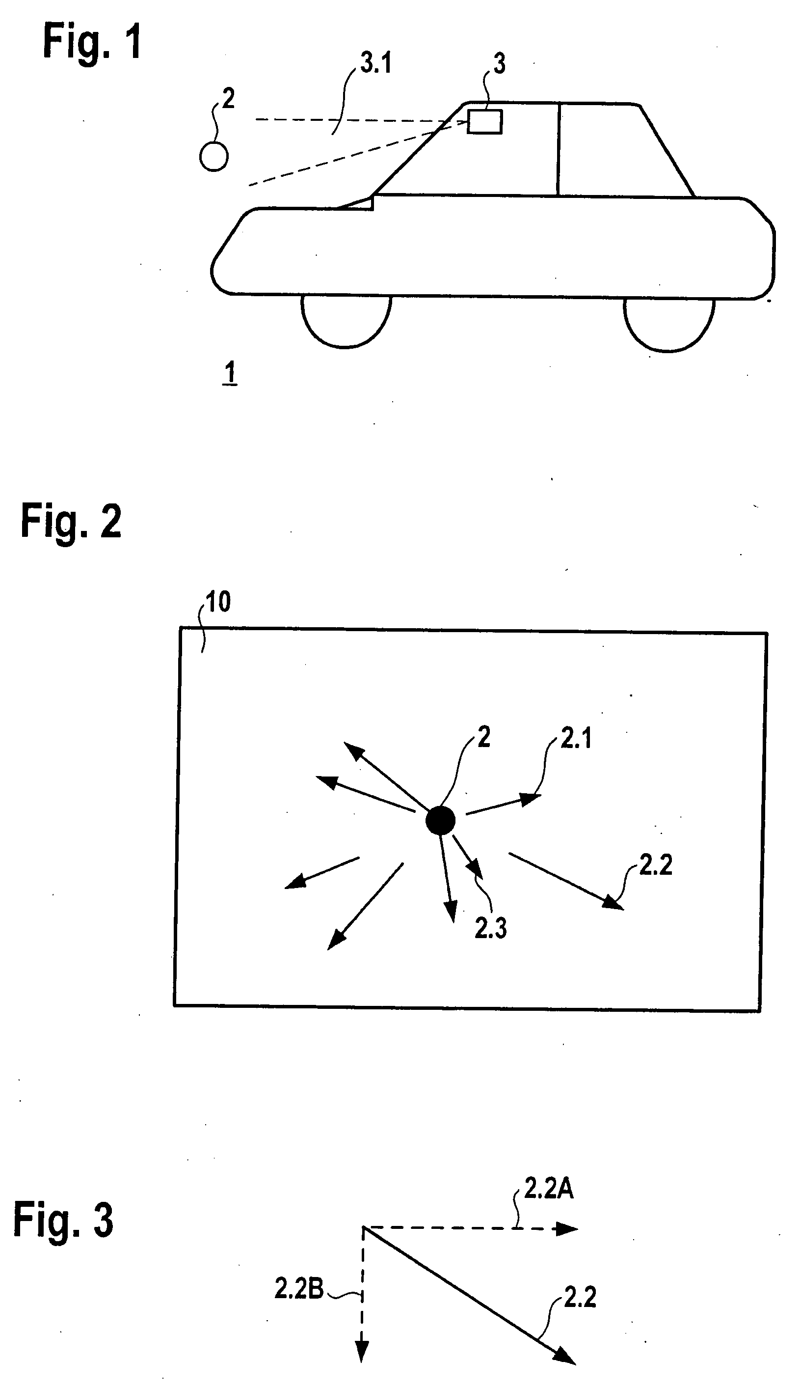
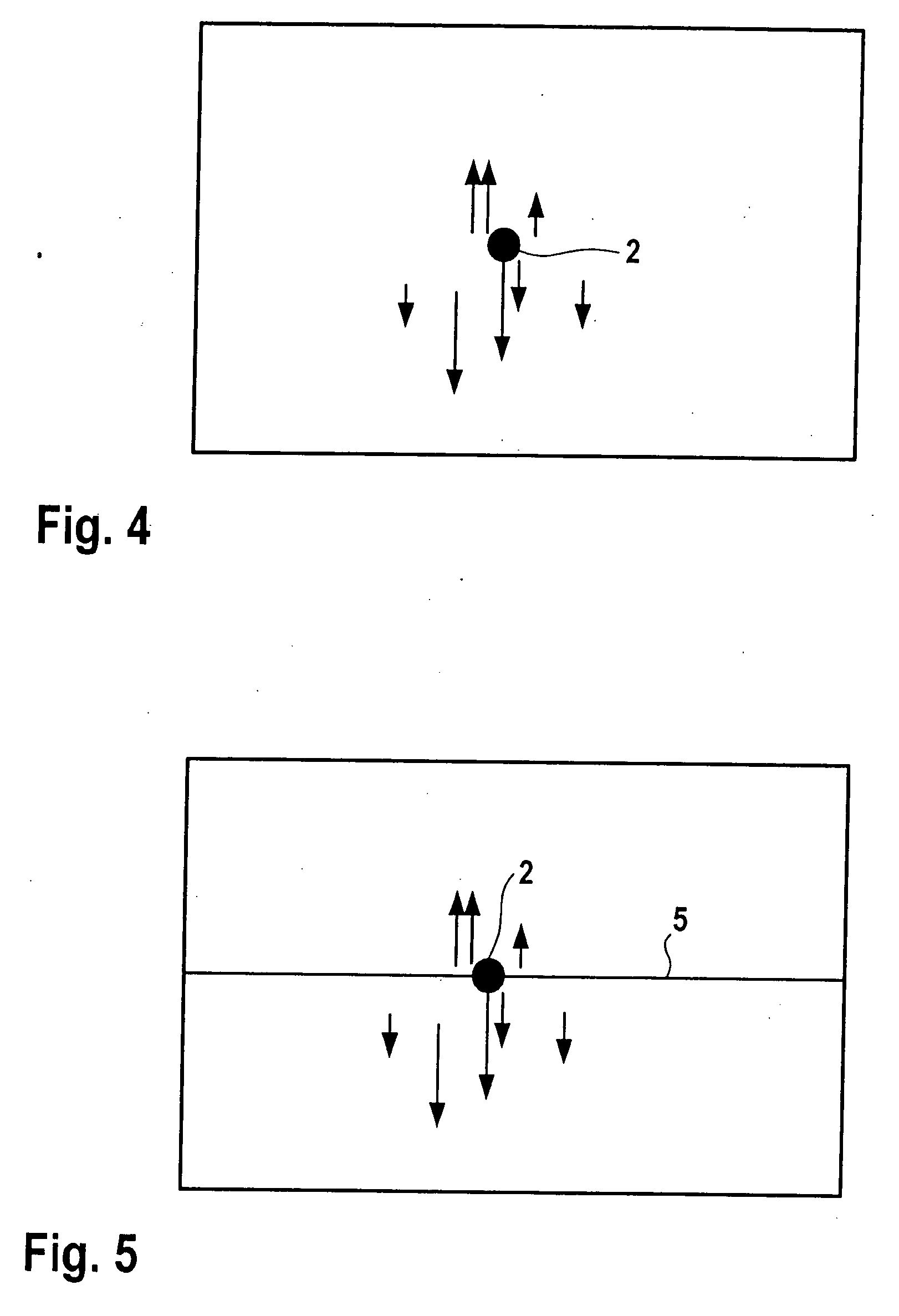
[0019] For many applications in the field of video-based driver assistance systems, which have at least one image recording system for detecting the vehicle surroundings, the detection of optical structures is of great significance. For the purposes of this application, the term optical structure includes, for example, horizontal lines within an image detected by the image recording system or outlines or contours of objects within an image. The optical structures recorded by the image recording system are used, for example, for calibrating the image recording system or for detecting the position and movement of the vehicle carrying the image recording system. Information derived from the detected optical structures is furthermore advantageous for the vehicle dynamics control system of the vehicle and in particular for lateral guidance as well. For the calibration of onboard image recording systems, expensive stationary methods are still being carried out in the production plants of ...


PUM


Abstract

A method for detecting an optical structure from image sequences of an image recording system. An optical flow field is derived from the image sequences of the image recording system. The vectors of the optical flow field are broken down into components by projection onto a coordinate system of the image recorded by the image recording system. At least one component of the flow vectors is analyzed for a change of direction. The image elements containing a change of direction of a vector component are connected to form a curve.

Description

FIELD OF THE INVENTION [0001] The present invention relates to a method for detecting an optical structure. BACKGROUND INFORMATION [0002] For the purposes of this application, the term optical structure includes, for example, lines, in particular horizontal lines, within an image or outlines or contours of objects within an image detected by an image recording system. Such optical structures are detected by an image recording system which is in particular installed in a vehicle. The optical structures recorded by the image recording system are used, for example, for calibrating the image recording system or for detecting the position and movement of the vehicle carrying the image recording system. Information derived from the detected optical structures may be advantageously used for the vehicle dynamics control system of the vehicle and in particular for lateral guidance as well. In motor vehicles, the use of image recording systems is intended for the detection of the vehicle surr...

Claims


Application Information

Patent Timeline
Patent Type & Authority Applications(United States)
IPC IPC(8): G08G1/04
CPCG06T7/2006G06T7/0018G06T7/215G06T7/80
Inventor MORITZ, RAINERMAASS, ALEXANDERSCHICK, JENSWUERZ-WESSEL, ALEXANDER
Owner ROBERT BOSCH GMBH
Why Eureka
Try Eureka