Apparatus for reducing pain during skin-puncturing procedures

a technology of skin-puncture and apparatus, which is applied in the field of apparatus for reducing pain during skin-puncture procedures, can solve the problems of limited effect, unsatisfactory pain reduction, and time-consuming, and achieve the effect of convenient and inexpensive utilization

Active Publication Date: 2017-01-10
BING INNOVATIONS
View PDF103 Cites 1 Cited by
  • Summary
  • Abstract
  • Description
  • Claims
  • Application Information

AI Technical Summary

Benefits of technology

[0005]It is a general object of the present invention to provide improvements to the invention described in the former application, especially regarding the retractor vibrator and single use or disposable tip described. Through the use of the improvements described and claimed herein further disadvantages will be overcome when injecting an anesthetic, serum, vitamins, vaccine, or other medical or dental efficacious liquids. In particular, it is an object of the present invention to provide improvements to the apparatus, article and method previously described that can be easily and inexpensively utilized during a medical, veterinary or dental procedure to almost completely or substantially eliminate the pain attendant an injection as it punctures the skin or flesh of the patient.
[0006]In keeping with the objects of the present invention, the present invention comprises an improved method, an improved article in the form of a disposable tip and an improved hand-held apparatus, in its preferred form of a retractor vibrator, for vibrating a skin or tissue area, and preferably at least two skin or tissue areas or a circular skin or tissue area, immediately at an injection site simultaneously with injection by needle of a liquid, such as, an anesthesia, serum, vitamins, vaccine, or other medical or dental efficacious liquids, into the skin or tissue at the injection site in a more effective and sanitary manner. The region of interest for a dentist is the entire oral mucosa area and underlying bone whereas the region of interest for a medical doctor is the whole body and underlying bone. Such a typical injection procedure may involve an injection of Lidocaine into a patient's gum or other tissue during a dental procedure.
[0007]Accordingly it is an object of the invention to provide an improved instrument for minimizing pain during administration by injection of a liquid, such as, an anesthetic comprising a main body, a detachable tip (novel article) cantilever mounted on the main body in a unique manner to prevent re-use of the tip and a vibration unit mounted in the main body when initiated to cause the tip to vibrate in a unique and novel manner. The tip is vibrated and has a free end characterized by a bifurcation to form two spaced projections defining a space between them, whereby the spaced projections can be placed in proximity to a preselected injection site on a human or animal and the tissue at said preselected injection site vibrated while an injection is given, and then continuing the vibration to massage the tissue to dissipate the injected liquid into the tissue and prevent tissue distension and swelling of the tissue. Preferably, the subsequent vibration is effected with more pressure on the tissue by the person injecting to effect better massaging. The subsequent vibration is most effective if the pressure applied is sufficient to sound bone beneath the tissue. An ordinarily skilled-in-the-art dentist can sense when he is applying pressure to tissue, such as the gums, and his instrument is touching the gums is in good contact or effectively hitting on underlying bone. When bone contact is sensed, the pressure is maintained for 1 to 30 seconds. The area of the injection site is lighted by the instrument in a unique way. Also, improved performance is obtained by pulsing the vibrations according to a preferred duty cycle, such about one second on and about 1 / 10th of a second off.
[0011]The objects of the invention are accomplished by an instrument for minimizing pain during administration by injection of a liquid, such as, an anesthetic comprising a main body having a forward end, a light-transmitting rod or lightpipe mounted in said body freely for vibration and projecting out of said forward end, a tip composed of a tip sleeve removably mounted on the forward end of said main body and a pronged tip member having a forward bifurcation defining a preselected injection site on a human or animal removably mounted on the lightpipe, said tip sleeve and pronged tip member being covered and held together by an elastic overmold while allowing light from said light rod to illuminate the injection site, a vibration unit mounted in the main body and coupled to said light rod such that when initiated imparts vibrations via said light rod to said pronged tip member. The instrument can comprise means for controlling the vibration unit for an on-off duty cycle, the duty cycle can be about 1 second on and about 1 / 10 second off. The pronged tip member may include at least one surface to act as a retractor. The tip sleeve and main body can include mutually coating members to prevent reuse of said tip. A music player may be included in the main body for playing music through a speaker. The light rod is preferably composed of polycarbonate and the light rod is held by an O-ring at the forward end in order to be vibrated freely.
[0012]The objects of the invention are further accomplished by providing an instrument for minimizing pain during administration by injection of a liquid, such as, an anesthetic comprising a main body having a forward end, a light rod mounted in said body extending toward said forward end, a single use disposable tip composed of a tip sleeve removably mounted on the forward end of said main body and a pronged tip member having a forward bifurcation defining a space that brackets a preselected injection site on a human or animal removably mounted on the light rod, said tip sleeve and pronged tip member being covered and held together by an elastic overmold while allowing light from said light rod to illuminate the injection site, a vibration unit mounted in the main body and coupled to said light rod such that when initiated imparts vibrations to said pronged tip member via said light rod, said tip and main body having mutually coacting elements such that once the tip is placed on said main body, its removal automatically prevents reuse of said tip. The instrument can include means for controlling the vibration unit for an on-off duty cycle, which is preferably set for a duty cycle is about 1 second on and about 1 / 10 second off. The pronged tip member can include at least one surface to act as a retractor.

Problems solved by technology

Although these procedures have some effect, they are either cumbersome, require some time to complete or are of limited effect and do not reduce the pain to a satisfactory level.

Method used


Image

  • Apparatus for reducing pain during skin-puncturing procedures
  • Apparatus for reducing pain during skin-puncturing procedures
  • Apparatus for reducing pain during skin-puncturing procedures

Examples


Embodiment Construction

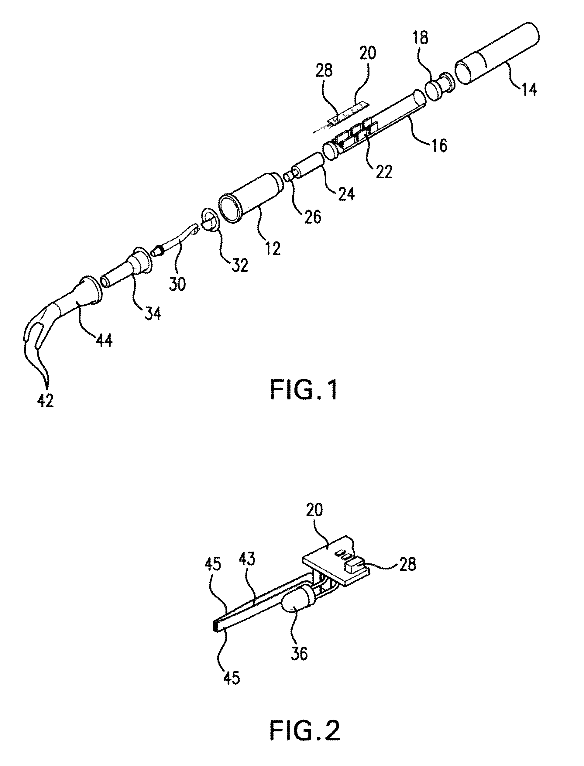
[0042]Referring to FIG. 1, an embodiment of the improved retractor vibrator is shown generally designated as 10 for performing the functions of the present invention, as will be explained hereinafter. In particular, retractor vibrator 10 is a handheld apparatus comprising a main body or handle 12 in the shape of a tube having a battery cover 14 as an end closure that is threaded to screw onto the open end of handle 12 in a complementary fit. Handle 12 is composed of hard plastic and partially receives a chassis 22, the uncovered portion being covered by the battery cover 14. Rechargeable batteries, not shown in FIG. 1, are located in battery compartment 16 of chassis 22. An induction coil 18 is mounted on the end of chassis 22 and positioned in the battery cover 14 to couple to a charge device in a conventional manner. A motor 24 driving a cam 26 is housed in the handle 12. Cam 26 includes a bore, see FIG. 23 (in the form of a ball socket 26a) whose axis is offset from the motor dri...


PUM


Abstract

An instrument, article and method are provided for minimizing pain during administration by injection of a liquid, such as, an anesthetic. The instrument has a forward end. A lightpipe mounted freely for vibration projects out of the forward end. The article, a single use tip, is composed of a tip sleeve removably mounted on the forward end of the instrument and a tip member removably mounted on the projecting lightpipe to vibrate a preselected injection site on a human or animal. The tip sleeve and tip member are covered by an elastic overmold that enables the tip member to vibrate freely with respect to the tip sleeve and light from the lightpipe to illuminate the injection site. A vibration unit mounted in the instrument is coupled to the lightpipe. The method is carried out by imparting vibrations and illumination via the lightpipe to the tip member.

Description

CROSS REFERENCE TO RELATED APPLICATIONS[0001]This application is a U.S. National Stage Application of International Application No. PCT / US2010 / 028858 filed Mar. 26, 2010, which claims priority to International Application No. PCT / US2009 / 066033 filed Nov. 29, 2009 and U.S. Provisional Application No. 61 / 163,945 filed Mar. 27, 2009. The contents of each of the above-identified applications are incorporated herein by reference.[0002]This application and the invention described herein is a continuation-part of PCT Application No. PCT / US09 / 66033 filed Nov. 29, 2009, which is a continuation-part of co-pending U.S. application Ser. No. 11 / 575,564 filed Mar. 19, 2007, both of which applications are here incorporated by reference in their entirety.FIELD OF INVENTION[0003]The invention relates to improvements to a method, article and apparatus for use in medical and dental procedures, and particularly to improvements to a method and apparatus in the form of a retractor vibrator and the articl...

Claims


Application Information

Patent Timeline
Patent Type & Authority Patents(United States)
IPC IPC(8): A61B17/20A61H7/00A61H23/02A61M5/42A61H13/00
CPCA61H23/0254A61H7/005A61M5/422A61H13/00A61H2201/0153A61H2201/0188A61H2201/1418A61H2201/1688A61H2203/03A61H2205/026A61M2205/43A61M2205/581A61M2205/59A61H23/008A61M5/42A61M19/00
Inventor GOLDBERG, STEVENSCHIFF, DAVIDEVANS, CHRISCOLEMAN, JOHN
Owner BING INNOVATIONS
Why Eureka
Try Eureka