Vehicle hood structure

a technology for hoods and vehicles, applied in the direction of vehicle components, pedestrian/occupant safety arrangements, superstructure sub-units, etc., can solve the problems of reduced absorption of collision energy, high deformation stiffness of beads in the vehicle front-rear direction against a front collision load, and reduced deformation stiffness of beads in the vehicle front-rear direction, etc., to achieve increased deformation resistance of the hood outer panel, the effect of increasing the propagation of stress in the vehicle front-

Active Publication Date: 2017-01-31
KOBE STEEL LTD
View PDF29 Cites 0 Cited by
  • Summary
  • Abstract
  • Description
  • Claims
  • Application Information

AI Technical Summary

Benefits of technology

[0006]However, there is a problem with the technique disclosed in Japanese Unexamined Patent Application Publication No. 2005-75163, Japanese Patent No. 4407755, and Japanese Unexamined Patent Application Publication No. 2005-239092 in that deformation stiffness of the beads in the vehicle front-rear direction against a front collision load is high, and accordingly, the vehicle hood structure is not easily bent. In order to address this, the height of the crush bead is increased to some degree. However, when the vehicle collides with the head of the pedestrian, the bending deformation occurs more easily than required from this crush bead as a starting point, and accordingly, the acceleration after the first peak is rapidly reduced. This causes another problem in that the amount of absorption of collision energy is reduced, and accordingly, the HIC value is degraded.
[0008]Accordingly, an object of the present invention is to provide a vehicle hood structure with which a vehicle hood stably undergoes bending deformation when a front collision with a vehicle occurs, and pedestrian protection performance can be further improved.
[0012]As described above, according to the present invention, the vehicle hood structure includes the hood inner panel and the hood outer panel. In the vehicle hood structure, the hood inner panel includes the substantially annular outer proximal surface coupled to the central region of the hood outer panel which is the region of the hood outer panel other than the outer peripheral portion of the hood outer panel. The hood inner panel also includes the plurality of beads that are disposed on the inner peripheral side of the substantially annular outer proximal surface, that extend in the vehicle width direction, that are substantially parallel to one another, and that project from the outer proximal surface to the lower side of the vehicle. The hood outer panel includes the at least one character line that extends substantially in the vehicle front-rear direction. The character line intersects the central line that extends in the vehicle width direction and that passes through the central point where the center of the hood outer panel in the vehicle front-rear direction and the center of the hood outer panel in the vehicle width direction are superposed on each other. The character line intersects the central line at the intersection point positioned within the region extending from the central point by 300 mm or less in the vehicle width direction. Accordingly, a vehicle hood structure can be realized with which a vehicle hood stably undergoes bending deformation when a front collision with a vehicle occurs and pedestrian protection performance can be further improved.
[0014]Furthermore, the hood outer panel includes the at least one character line at the specified position near the center of the hood where the acceleration is likely to be excessively reduced in the above-described hood structure including the hood inner panel after the first peak when the collision with the head occurs. The character line allows deformation resistance of the hood outer panel to be increased so that bending deformation of the hood inner panel does not occur more than required. In addition, the propagation of the stress in the vehicle front-rear direction can be increased through this character line. Thus, energy produced when the collision with the head occurs can be quickly transmitted in the vehicle front-rear direction, and a region that receives an impact load applied when the collision with the head occurs can be increased. Accordingly, an ideal waveform in which the first acceleration peak is high and quick reduction of the acceleration after the first acceleration peak is suppressed can be easily realized. This allows the amount of absorption of collision energy to be increased and the second acceleration peak to be reduced. Thus, the HIC value can be reduced.

Problems solved by technology

However, there is a problem with the technique disclosed in Japanese Unexamined Patent Application Publication No. 2005-75163, Japanese Patent No. 4407755, and Japanese Unexamined Patent Application Publication No. 2005-239092 in that deformation stiffness of the beads in the vehicle front-rear direction against a front collision load is high, and accordingly, the vehicle hood structure is not easily bent.
This causes another problem in that the amount of absorption of collision energy is reduced, and accordingly, the HIC value is degraded.
Thus, the vehicle hood structure is likely to undergo bending deformation.
This causes a problem in that the target HIC value is largely degraded compared to a satisfactory HIC value.
Thus, there is a problem in that the second acceleration peak caused by this contact is increased (see FIG. 10).
This in turn causes a problem in that the increase in the second acceleration peak leads to degradation of the HIC (head injury criterion) value and degradation of the pedestrian protection performance.

Method used


Image

  • Vehicle hood structure
  • Vehicle hood structure
  • Vehicle hood structure

Examples


embodiment

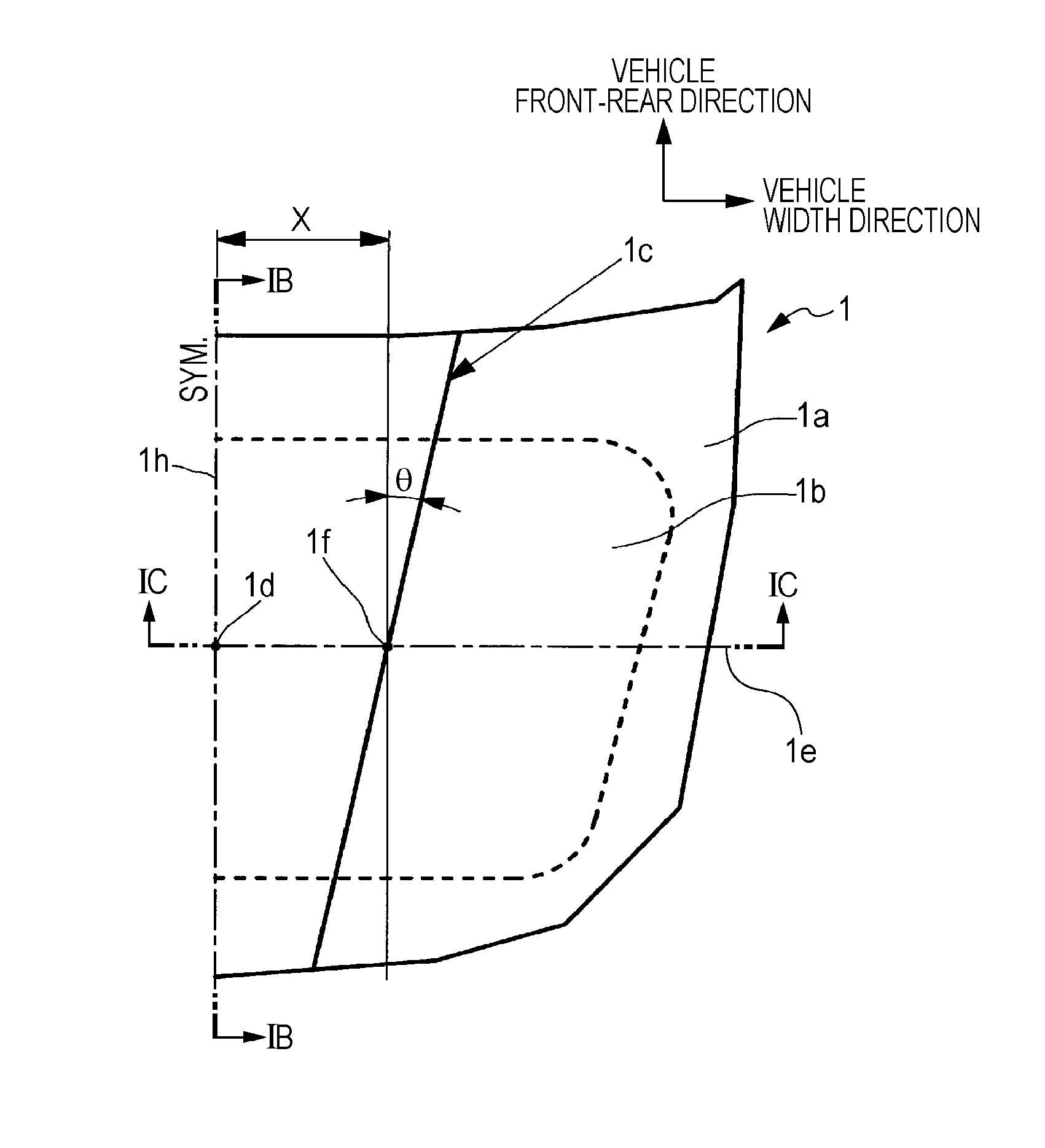
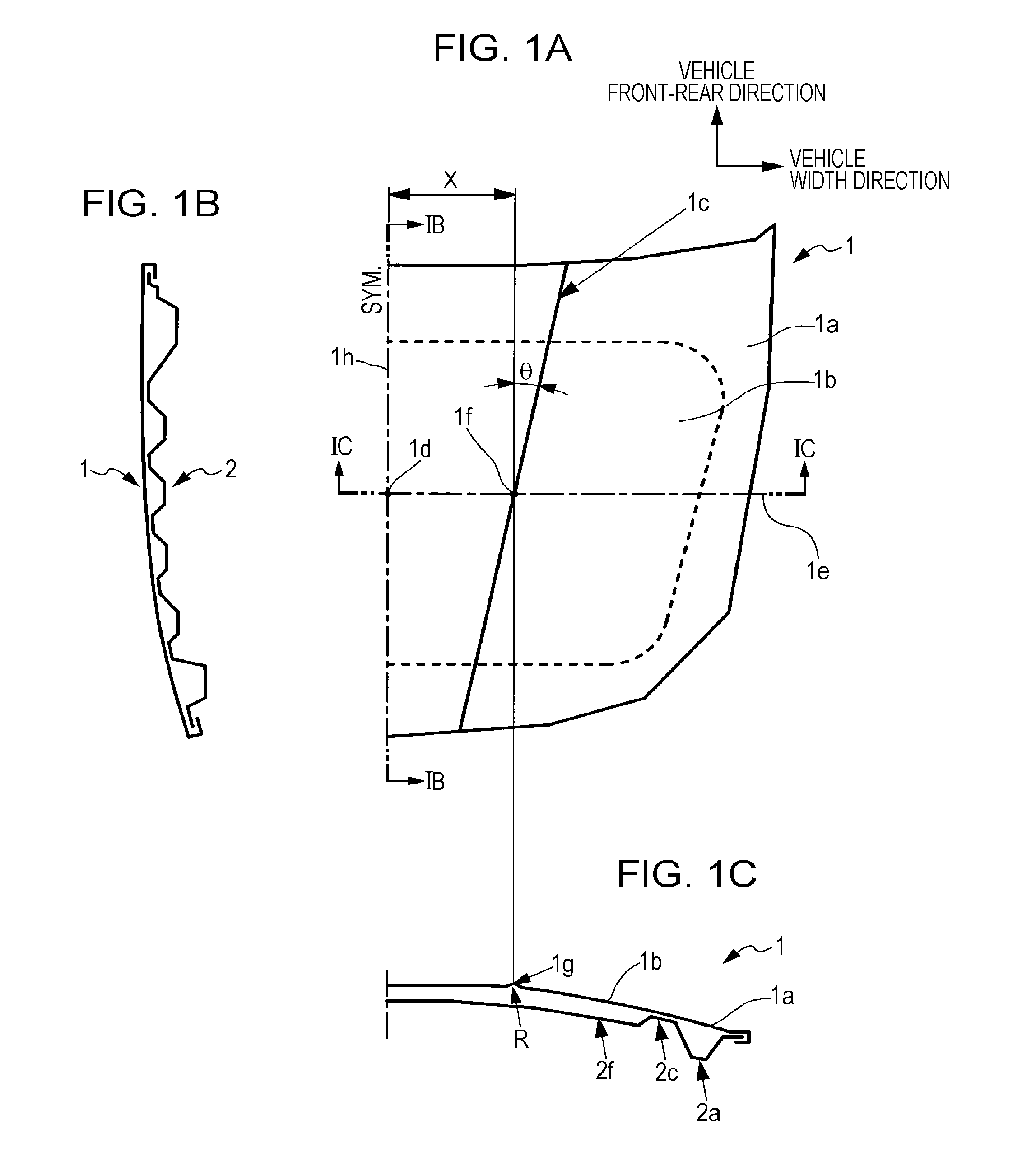
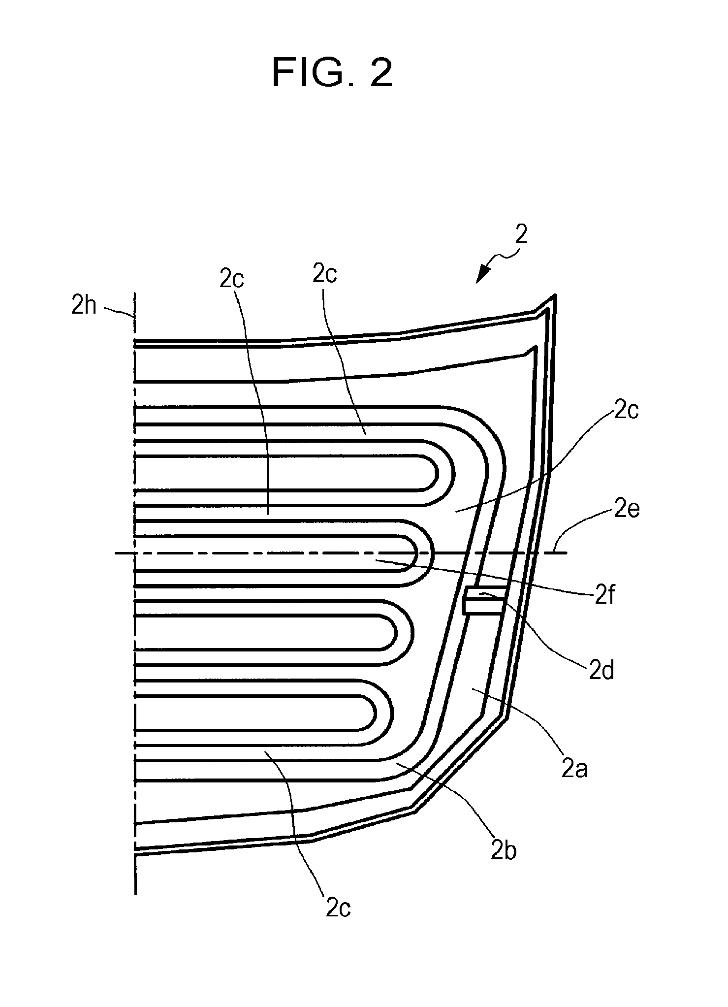
[0026]FIGS. 1A to 1C illustrate a vehicle hood structure according to an embodiment of the present invention, and out of FIGS. 1A to 1C, FIG. 1A is a plan view of the vehicle hood structure, FIG. 1B is a sectional view of the vehicle hood structure illustrated in FIG. 1A taken along line IB-IB illustrated in FIG. 1A, and FIG. 1C is a sectional view of the vehicle hood structure illustrated in FIG. 1A taken along line IC-IC illustrated in FIG. 1A. FIG. 2 is a schematic perspective view of a hood inner panel of the vehicle hood structure illustrated in FIG. 1A (with a hood outer panel removed). FIG. 3 is an explanatory view of three impact points (may also be referred to as “pedestrian protection performance test points” hereafter) where impact is applied to the vehicle hood structure, the impact points being indicated on the hood inner panel illustrated in FIG. 2. FIG. 4 is a waveform chart illustrating the relationship between a stroke and acceleration at three impact points illustr...

example

[0034]According to an example, the hood outer panel 1 illustrated in FIG. 1A is provided with the character lines 1c each provided on a corresponding one of the left and right sides. The vehicle-width-direction distance between the intersection point 1f of each of the character lines 1c and the central point 1d is 150 mm and the angle θ relative to the character line 1c is 10°. The hood outer panel 1 is coupled to the hood inner panel 2 illustrated in FIG. 2 by mastic. The radius of curvature R of the projecting top portion 1g of the character line 1c is 8 mm. With the vehicle hood structure having such a structure, when the head collides with three pedestrian protection performance test points (a, b, and c) as illustrated in FIG. 3 as described above, the relationship between the acceleration and the stroke applied to the head of an pedestrian is as illustrated in FIG. 4.

[0035]By adopting a structure such as the structure of the present example, when the head collides with a region...


PUM


Abstract

A vehicle hood structure includes a hood outer panel and a hood inner panel. The hood outer panel includes at least one character line extending substantially in a vehicle front-rear direction. The character line intersects a central line that extends in a vehicle width direction and that passes through a central point where a center of the hood outer panel in the vehicle front-rear direction and a center of the hood outer panel in the vehicle width direction are superposed on each other. The character line intersects the central line at an intersection point positioned within a region extending from the central point by 300 mm or less in the vehicle width direction.

Description

BACKGROUND OF THE INVENTION[0001]1. Field of the Invention[0002]The present invention relates to a vehicle hood structure that includes a hood inner panel and a hood outer panel and that has good pedestrian protection performance when a vehicle collides with a pedestrian and good front collision performance when the vehicle collides with another vehicle.[0003]2. Description of the Related Art[0004]There are many design requirements to be satisfied other than pedestrian protection performance for a vehicle hood structure including a hood inner panel and a hood outer panel. In particular, when a front collision with another vehicle occurs, it is required that the vehicle hood structure be deformed such that the center of the vehicle hood structure rises and is bent into an angular shape in sectional view so as to prevent entrance into the vehicle. In order to facilitate this bending deformation, a structure that includes a crush bead extending in the vehicle width direction has been p...

Claims


Application Information

Patent Timeline
Patent Type & Authority Patents(United States)
IPC IPC(8): B62D25/00B62D25/12
CPCB62D25/12B60R21/34B62D25/10B62D25/105
Inventor YOSHIDA, MASATOSHIKASHIMA, HIROKO
Owner KOBE STEEL LTD
Why Eureka
Try Eureka