In-band signaling for network protection switching

a technology of in-band signaling and network protection, applied in the direction of data switching network, digital transmission, electrical equipment, etc., can solve problems such as data loss and inacceptable delays

Active Publication Date: 2017-02-07
CIENA
View PDF13 Cites 2 Cited by
  • Summary
  • Abstract
  • Description
  • Claims
  • Application Information

AI Technical Summary

Benefits of technology

[0006]FIG. 2 is a schematic block diagram of aspects of out-of-band control signaling to coordinate the switching of a traffic signal to a protection channel among the multiple cards at a node, resulting in potentially problematic latency times;

Problems solved by technology

Involvement by a network administrator to repair a damaged communications network can result in unacceptable delays and lost data.
However, the control signaling involved in coordinating a determination to transfer a traffic signal from a compromised channel often pushes and / or transgresses this upper boundary.

Method used


Image

  • In-band signaling for network protection switching
  • In-band signaling for network protection switching
  • In-band signaling for network protection switching

Examples


Embodiment Construction

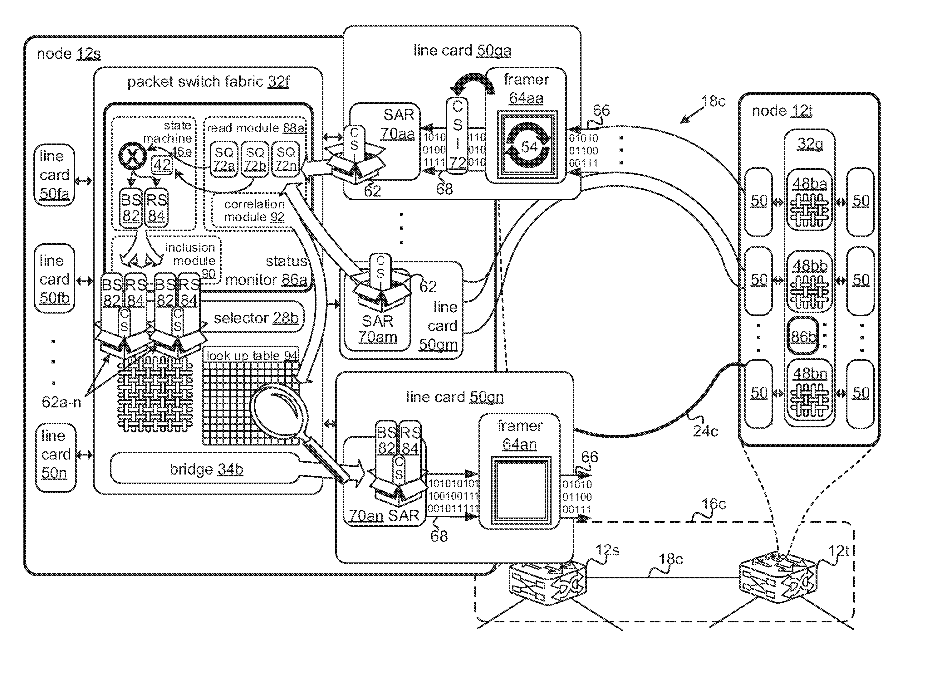
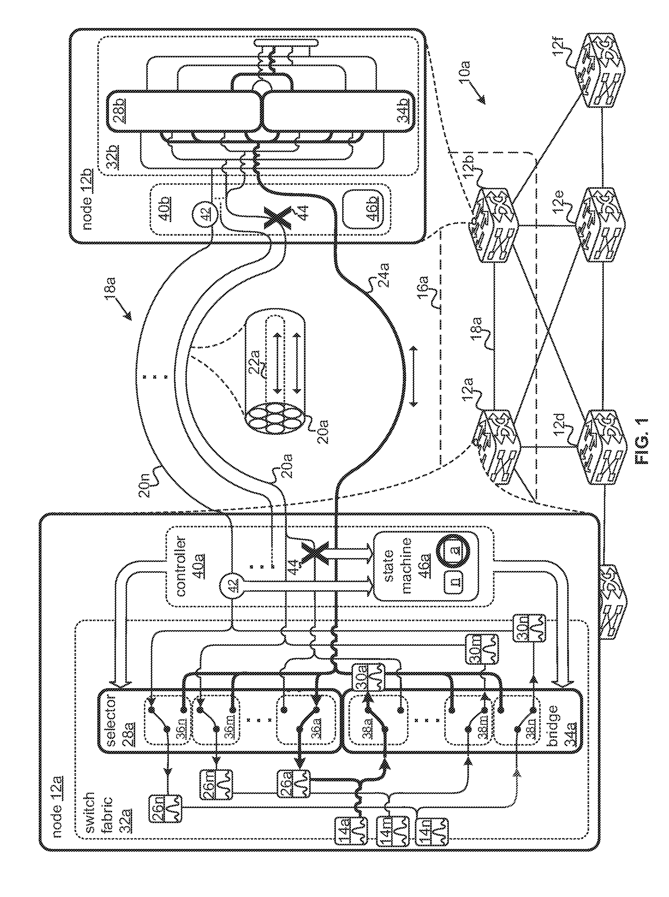
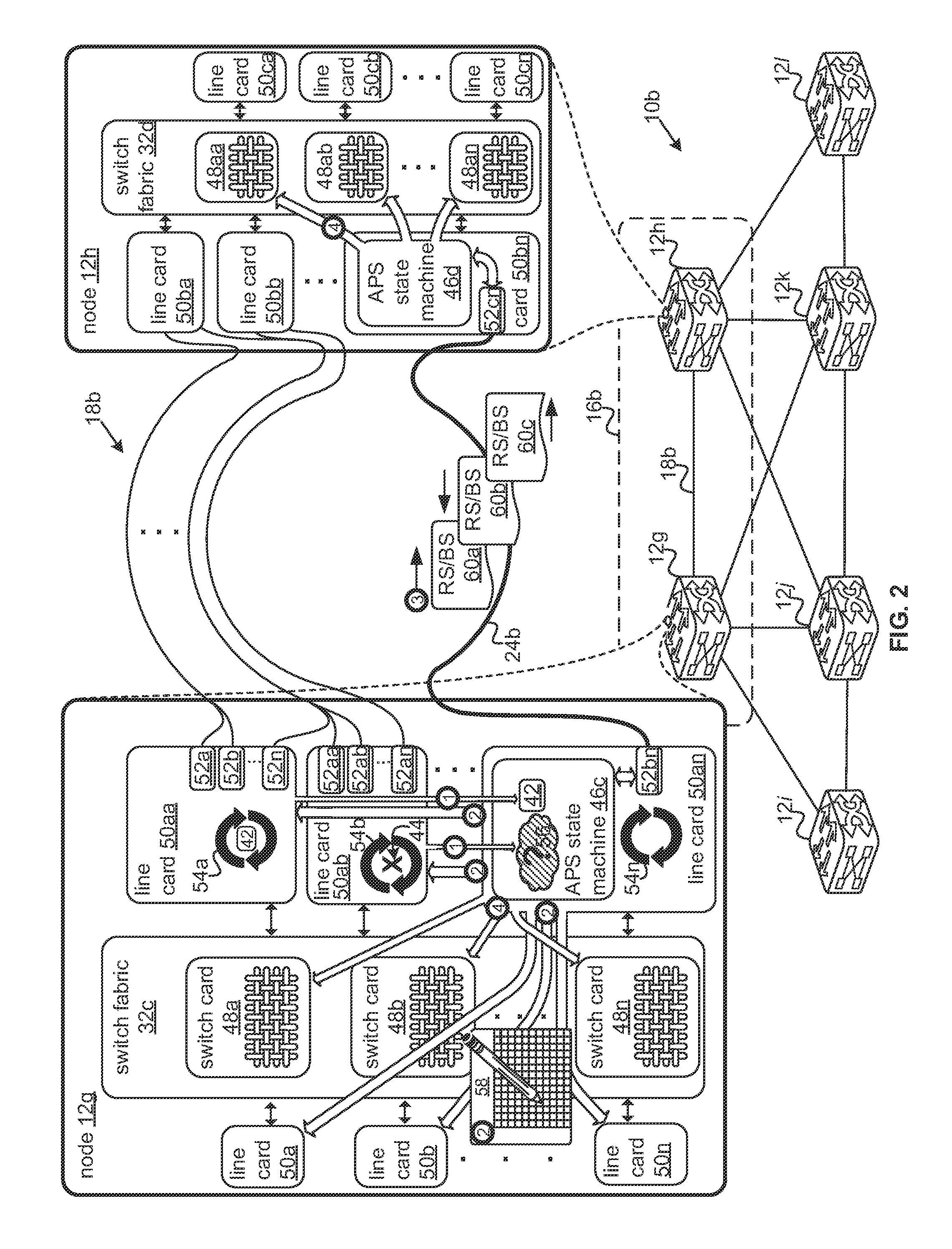
[0013]It will be readily understood that the components of the present invention, as generally described and illustrated in the Figures herein, can be arranged and designed in a wide variety of different configurations. Thus, the following more detailed description of the embodiments of the invention, as represented in the figures, is not intended to limit the scope of the invention, as claimed, but is merely representative of certain examples of presently contemplated embodiments in accordance with the invention. The presently described embodiments will be best understood by reference to the drawings, wherein like parts are designated by like numerals throughout. In some cases, particular instances of an element may be identified with a number followed by a letter, where the letter may change throughout the figures, indicating differing instances of the element with the same or varying attributes. References to elements by number only may refer more generally to a class of such ele...


PUM


Abstract

Systems are disclosed for automated protection switching enabled by in-band signaling. A status monitor coupled to a switch fabric may be operable to read signal quality information from cells packet-switched over the fabric, the cells carrying traffic signals from one or more working channels between two network nodes. The status monitor may apply a protection algorithm to the signal quality information to determine whether a traffic signal on a working channel meets requirements indicative of channel failure or degradation sufficient to move the traffic signal to an additional protection channel between the two nodes. The status monitor may encode a request to transfer this traffic signal in cells switched by the fabric. In some examples, this request may be encoded in an optional user and fabric overhead field of cells consistent with the Optical-Transport Network (OTN) over Packet Fabric Protocol (OFP).

Description

FIELD OF THE INVENTION[0001]This invention relates to the protection of traffic signals in a network and more particularly to the architecture of control signaling to coordinate the protection of a traffic signal between two network nodes by transferring the traffic signal from a compromised working channel to an additional protection channel.BACKGROUND OF THE INVENTION[0002]Involvement by a network administrator to repair a damaged communications network can result in unacceptable delays and lost data. Reliable communication networks take into account potential degradation or failure of the channels over which traffic signals are transported through redundancy in the network. The need to quickly repair communication of networks leads to the automation of the controls by which redundancies may be accessed.[0003]The objective of such automation is to transfer a traffic signal to a redundant, or protection, channel from a degraded or failed channel with small enough latencies that the...

Claims


Application Information

Patent Timeline
Patent Type & Authority Patents(United States)
IPC IPC(8): H04L12/26H04L12/24
CPCH04L43/08H04L41/0659H04L41/0672H04L41/0695H04L41/0661
Inventor BELANGER, MARTIN G.
Owner CIENA
Why Eureka
Try Eureka