Supercharge Your Innovation With Domain-Expert AI Agents!

Cutting element, tool and method of cutting within a borehole

a cutting element and borehole technology, applied in the direction of constructions, etc., can solve the problem that the top elements tend to slide off due to gravity

Active Publication Date: 2017-02-28
BAKER HUGHES HLDG LLC
View PDF13 Cites 0 Cited by
  • Summary
  • Abstract
  • Description
  • Claims
  • Application Information

AI Technical Summary

Benefits of technology

This design enables efficient and durable cutting by maintaining consistent cutting angles and preventing sliding, resulting in improved tool longevity and performance, especially in downhole applications.

Problems solved by technology

Furthermore, angles of cutting surfaces relative to the target material are randomized and consequently few are near preferred angles that facilitate efficient cutting.
If these elements are leaning at the desired angle, when the second layer is stacked on top, the top elements will tend to slide off due to gravity.

Method used


Image

  • Cutting element, tool and method of cutting within a borehole
  • Cutting element, tool and method of cutting within a borehole
  • Cutting element, tool and method of cutting within a borehole

Examples


Embodiment Construction

[0015]A detailed description of one or more embodiments of the disclosed apparatus and method are presented herein by way of exemplification and not limitation with reference to the Figures.

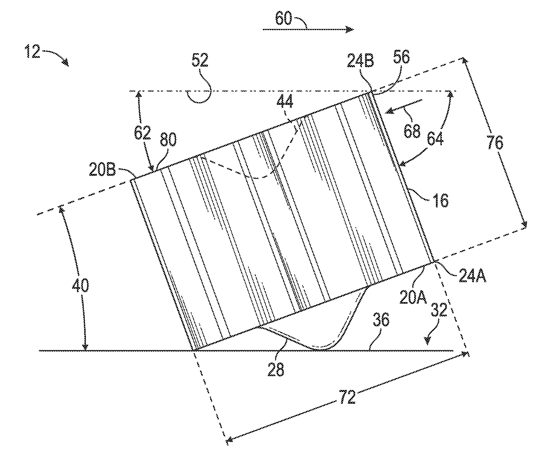
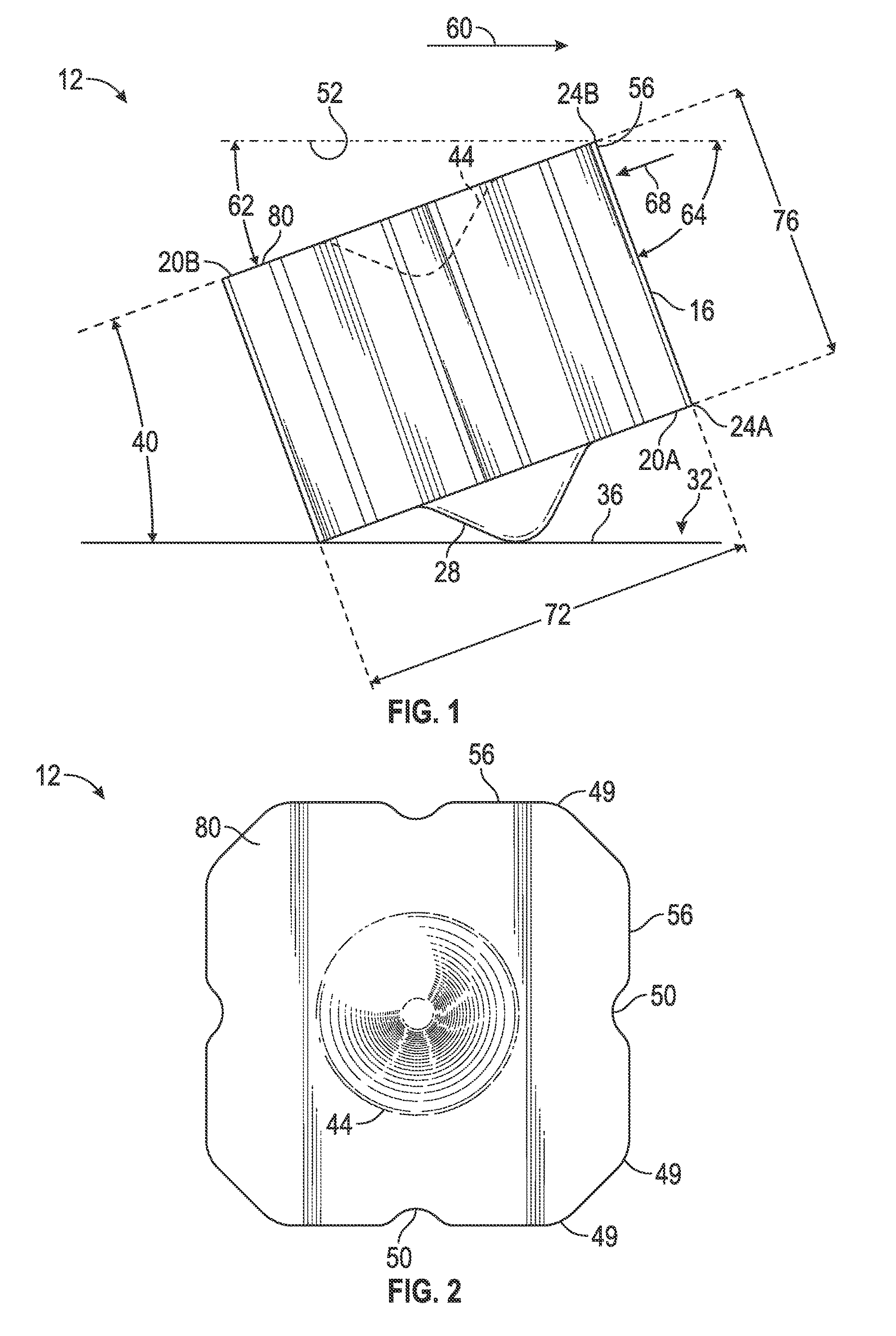
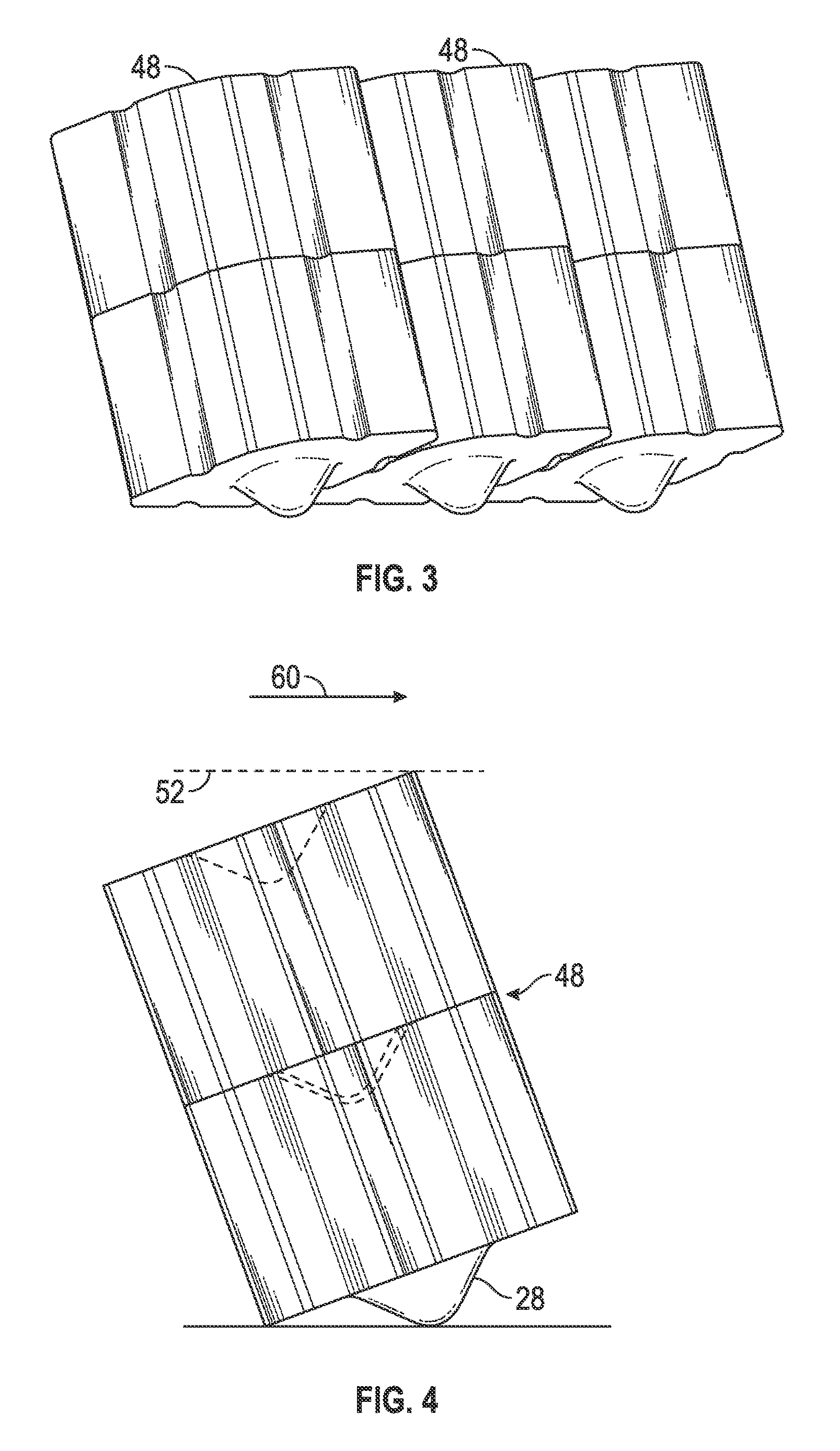
[0016]Referring to FIGS. 1 and 2, an embodiment of a cutting element disclosed herein is illustrated at 12. The cutting element 12 includes a body 16 and a support 28. The body 16 has a first plane 20A defining a plurality of edges 24A and a second plane 20B defining a plurality of edges 24B. The support 28 extends beyond the first plane 20A such that the cutting element 12 is restable upon a planar surface 32 with at least one of the edges 24A and the support 28 being simultaneously in contact with the planar surface 32. The planar surface 32 may be on a cutting tool 36 to which the cutting element 12 is attachable. It should be noted that a tool may have a surface that is not planar to which the cutting elements 12, 48 (see FIGS. 3-5) are attachable as well. With the cutting element 12 resting ...


PUM


Abstract

A cutting element includes, a body having two planes, each of the two planes defining a plurality of edges, and a support extending from a first of the two planes. The support and the body are configured such that when the cutting element is resting against a planar surface such that at least one of the plurality of edges and the support are in contact with the planar surface, the second of the two planes forms an acute angle with the planar surface. Additionally, a protrusion extends laterally from at least one face of the body and an indentation is formed in at least one face of the body. The protrusion and the indentation are complementary to one another such that the protrusion of a first of the cutting elements is positionable within the indentation of a second of the cutting elements.

Description

CROSS REFERENCE TO RELATED APPLICATIONS[0001]This application is a continuation-in-part of U.S. application Ser. No. 13 / 530,942 filed Jun. 22, 2012, the disclosure of which is incorporated by reference herein in its entirety.BACKGROUND[0002]Cutting tools, such as mills used in downhole applications, for example, can be made with a plurality of cutting elements that are adhered to a surface of a tool. The cutting elements can be randomly shaped particles made by fracturing larger pieces. Alternately, cutting elements can be precisely formed into repeatable shapes using processes such as pressing and sintering, for example. Regardless of the process employed to make the individual cutting elements, the elements are typically adhered to the mill with random orientations. These random orientations create disparities in maximum heights relative to a surface of the mill. Furthermore, angles of cutting surfaces relative to the target material are randomized and consequently few are near pr...

Claims


Application Information

Patent Timeline
Patent Type & Authority Patents(United States)
IPC IPC(8): E21B10/573E21B10/43
CPCE21B10/5735E21B10/43E21B10/633
Inventor STOWE, CALVIN J.MODY, RUSTOM K.
Owner BAKER HUGHES HLDG LLC
Features
  • R&D
  • Intellectual Property
  • Life Sciences
  • Materials
  • Tech Scout
  • Unparalleled Data Quality
  • Higher Quality Content
  • 60% Fewer Hallucinations
Learn More