
Maintaining state information in a multi-component, event-driven state machine

a state machine and event-driven technology, applied in the field of data processing systems, can solve the problems of increasing the difficulty of managing the state machine, cost and complexity, and increasing the difficulty of the state machin

Inactive Publication Date: 2017-03-07
INT BUSINESS MASCH CORP
View PDF6 Cites 0 Cited by
  • Summary
  • Abstract
  • Description
  • Claims
  • Application Information

AI Technical Summary

Benefits of technology

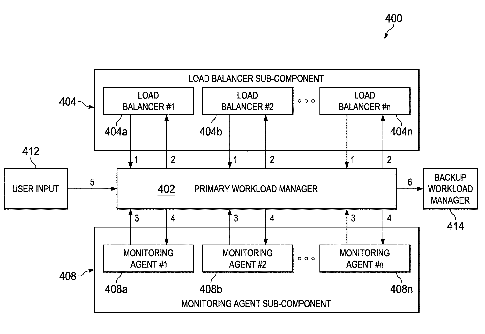
[0007]Generally, this disclosure describes a method that allows for maintaining correct states of all sub-components in a state machine, even as sub-components leave the state machine and later rejoin in some previous state. Preferably, this is achieved without requiring the system to remember the states of all sub-components or a log of every event that was fed into the state machine. Thus, the method does not require any knowledge of the previous state of the sub-components nor the need to preserve a complete log of events that were fed into the state machine.
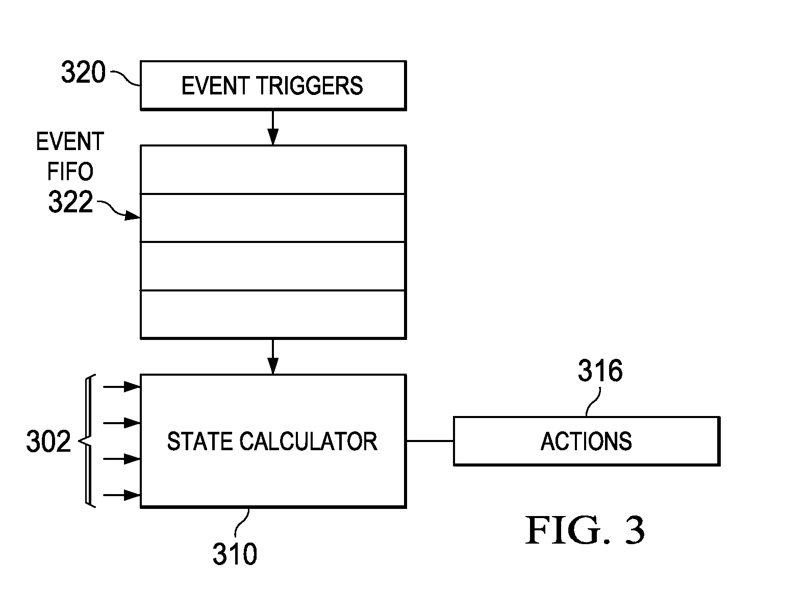
[0009]The transition information is “minimized” according to a pruning scheme. To this end, only the events that cause a state transition for this sub-component need to be recorded by the main component and replayed. A triggered event that reverses a state transitioning as a result of a prior event, or if the new event is a superset of a prior event, can allow the prior event to be “pruned” from the log of events for this sub-component. As the state machine is fed a continuous set of triggering events, this “pruning” of the log for the sub-component makes management of the state machine easier, as fewer events need to be saved for each sub-component.

Problems solved by technology

A significant challenge in managing a state machine is trying to maintain a time-consistent state of each of the sub-components of the overall state machine, especially when events are being fed into the main component and sub-components (or even the main component) have temporarily removed themselves from the state machine.
This is a costly and complex requirement, and one that increases the difficulty in managing the state machine.

Method used


Image

  • Maintaining state information in a multi-component, event-driven state machine
  • Maintaining state information in a multi-component, event-driven state machine
  • Maintaining state information in a multi-component, event-driven state machine

Examples


Embodiment Construction

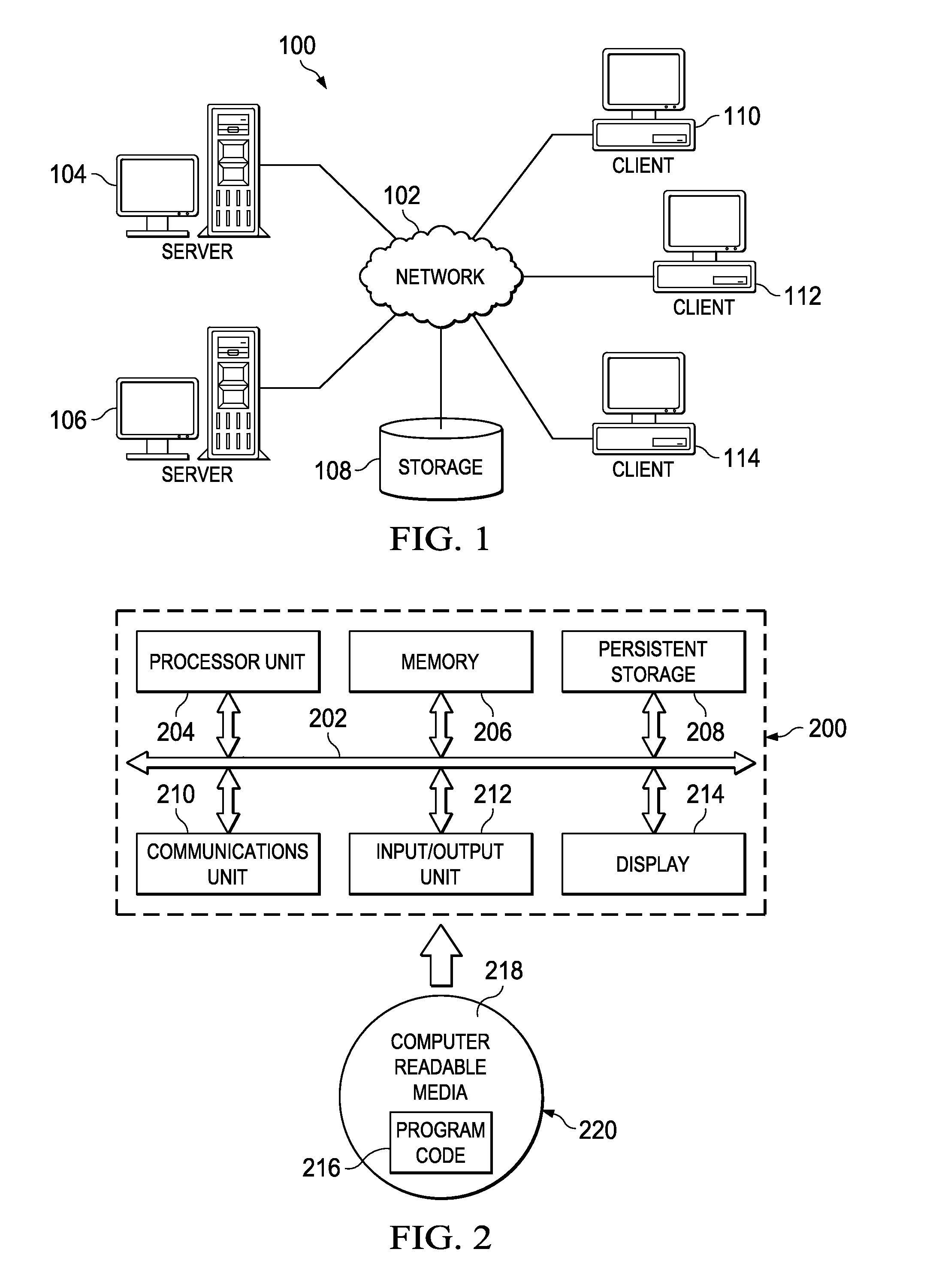
[0018]With reference now to the drawings and in particular with reference to FIGS. 1-2, exemplary diagrams of data processing environments are provided in which illustrative embodiments of the disclosure may be implemented. It should be appreciated that FIGS. 1-2 are only exemplary and are not intended to assert or imply any limitation with regard to the environments in which aspects or embodiments of the disclosed subject matter may be implemented. Many modifications to the depicted environments may be made without departing from the spirit and scope of the present invention.

Client-Server Technologies

[0019]With reference now to the drawings, FIG. 1 depicts a pictorial representation of an exemplary distributed data processing system in which aspects of the illustrative embodiments may be implemented. Distributed data processing system 100 may include a network of computers in which aspects of the illustrative embodiments may be implemented. The distributed data processing system 10...


PUM


Abstract

A method, apparatus and computer program product that allows for maintaining correct states of all sub-components in a state machine, even as sub-components leave the state machine and later rejoin in some previous state. Preferably, this is achieved without requiring the system to remember the states of all sub-components or a log of every event that was fed into the state machine. Thus, the technique does not require any knowledge of the previous state of the sub-components nor the need to preserve a complete log of events that were fed into the state machine. The state machine may be used to enhance the operation of a technological process, such as a workload management environment.

Description

BACKGROUND OF THE INVENTION[0001]Technical Field[0002]This disclosure relates generally to data processing systems and, in particular, to state machines.[0003]Background of the Related Art[0004]State machines, also referred to as “finite state machines,” are computing devices designed with the operational states required to solve a specific problem. In a typical state machine, events are fed into the system to transition the state machine from one state to another. In more complex state machines, the state machine is made up of different sub-components; the sub-components (or some of them) could be on the same system as a main component, or the sub-components can be spread across different systems that can be located a geographical distance apart from each other. These different sub-components often feed events into the main component of the state machine, as well as transition into states of their own, e.g., based on events fed from other sub-components of the state machine.[0005]A...

Claims


Application Information

Patent Timeline
Patent Type & Authority Patents(United States)
IPC IPC(8): G06F9/44G06F9/50G06F9/54
CPCG06F9/444G06F9/5083G06F9/542G06F9/4498
Inventor FITZPATRICK, MICHAEL GERARDARROWOOD, JR., ANDREW HILLIARDMCAFEE, GARY OWENHUANG, SUE L.
Owner INT BUSINESS MASCH CORP
Learn More