Coring tools and related methods

a technology of coring tools and core samples, applied in the field of coring tools, can solve the problems of affecting the quality of coring tools, affecting the accuracy of coring tools,

Active Publication Date: 2017-03-21
BAKER HUGHES HLDG LLC
View PDF14 Cites 5 Cited by
  • Summary
  • Abstract
  • Description
  • Claims
  • Application Information

AI Technical Summary

Problems solved by technology

Prior art core barrel assemblies are prone to damage core samples in various ways during operation.
After the core catcher engages the core, withdrawal of the core barrel assembly from the well bore often causes the core to fracture at a location just below the core catcher instead of at the bottom of the well bore, leaving a stump of core material within the well bore.
This stump may be problematic for several reasons.
For example, this stump may dislocate the core catcher, cause the core barrel assembly to jam, or otherwise interfere with a smooth withdrawal of the core sample from the well bore.
Moreover, the stump represents a portion of the core sample that was not recovered and delivered to the surface, resulting in a potential loss of valuable information regarding the formation material within the well bore.
Additionally, the stump may interfere with subsequent operations within the well bore, such as drilling, reaming, or additional coring operations.
Another way in which prior art core barrel assemblies damage core samples is by exposing the core to deleterious amounts of drilling fluid.
For example, a throat discharge channel having a high Total Flow Area (“TFA”), measured in a plane transverse to a longitudinal axis of the core barrel assembly, can create significant problems during coring operations, especially when coring in relatively soft to medium hard formations, or in unconsolidated formations.
Such drilling fluid can invade and contaminate the core itself.
For soft or unconsolidated formations, these drilling fluids invading the core may wash away, or otherwise severely disturb, the material of the core.
The core may be so badly damaged by the drilling fluid invasion that standard tests for permeability, porosity, and other characteristics produce unreliable results, or cannot be performed at all.
For harder formations, drilling fluid coming into contact with the core may still penetrate the core, contaminating the core and making it difficult to obtain reliable test data.
The problems associated with stump length and fluid invasion of core samples described above may be a result, at least in part, of the material comprising the bit body of a core barrel assembly.
However, the dimensional tolerances of metal matrix core bits (including inner surface diameter, gap width of the throat discharge channel, TFA of the face discharge channels and depth of the junk slots) are severely limited by the strength of the metal matrix material.

Method used


Image

  • Coring tools and related methods
  • Coring tools and related methods
  • Coring tools and related methods

Examples


embodiment 1

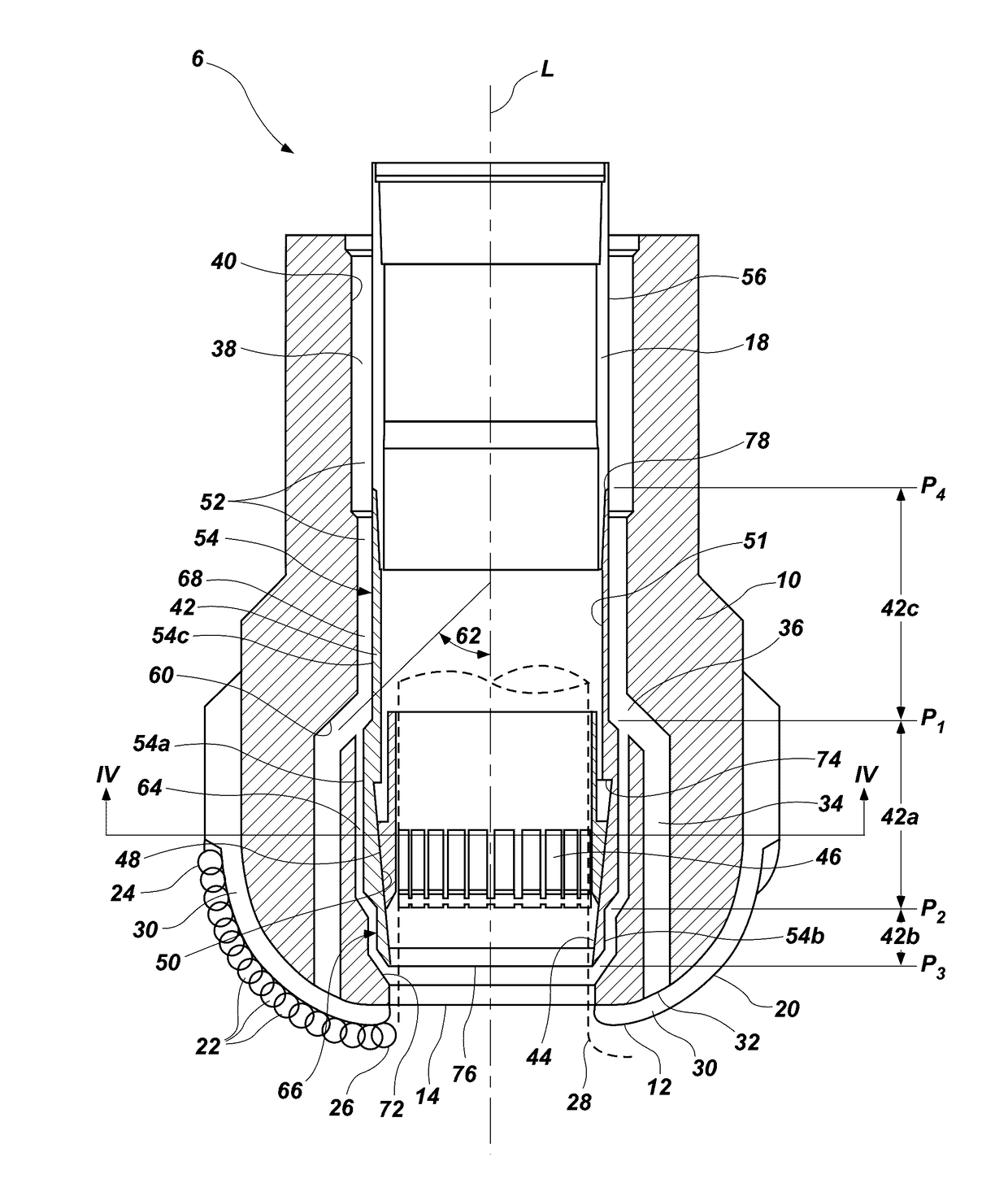
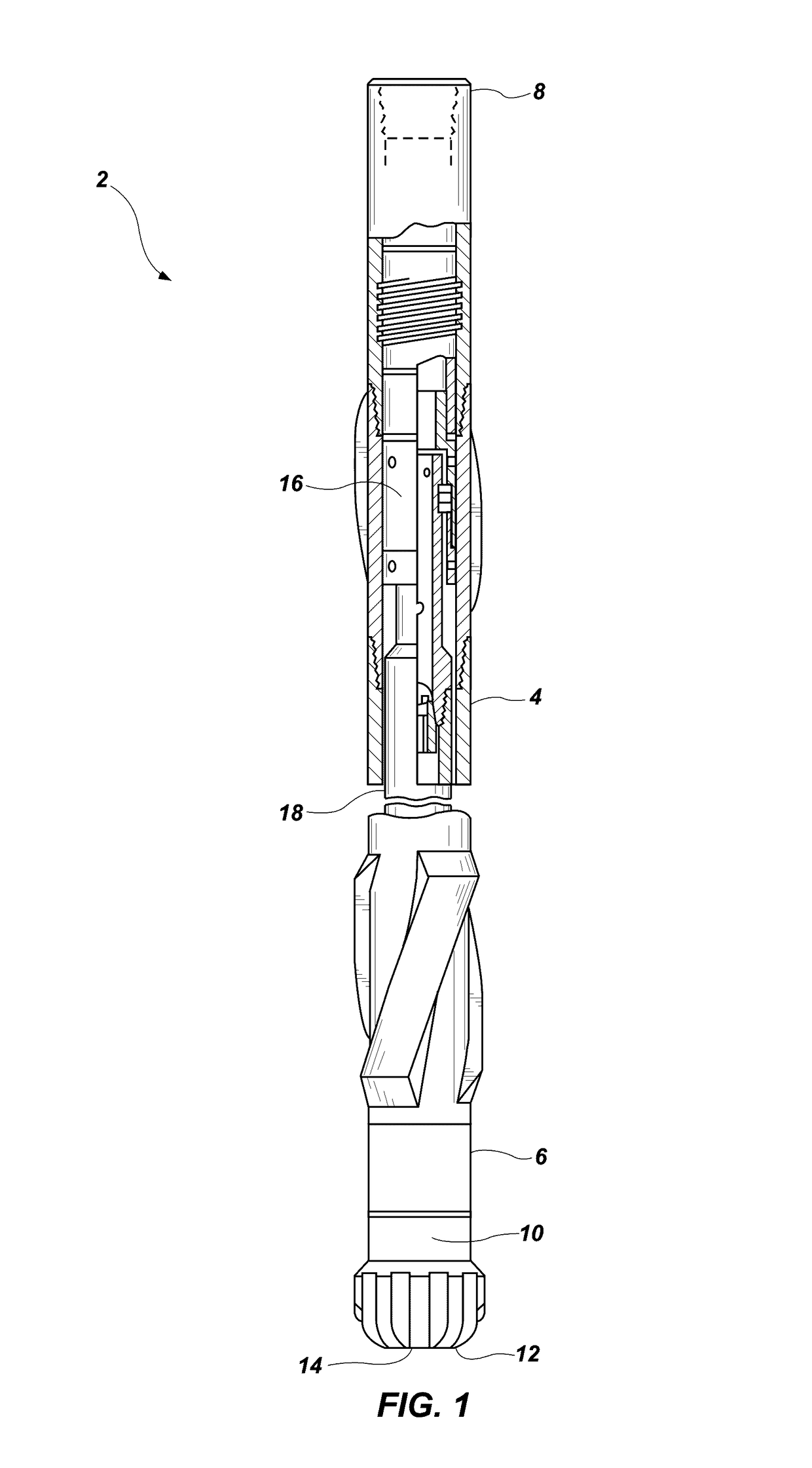
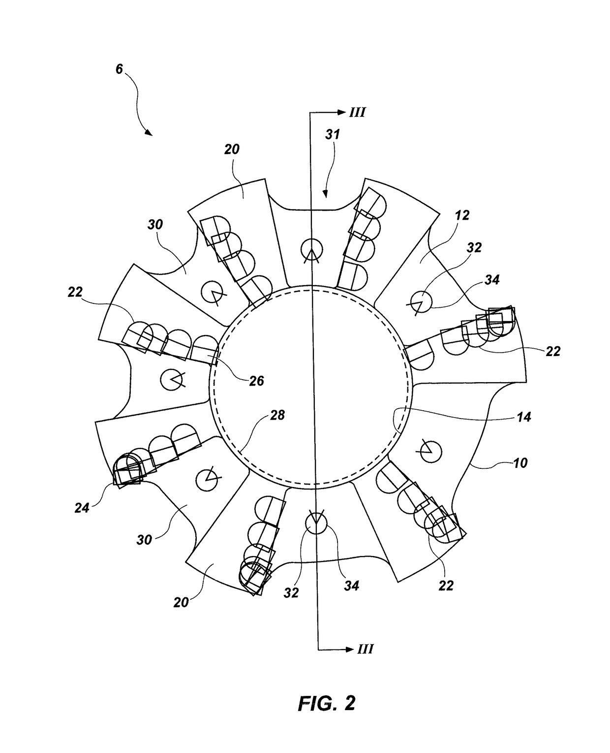
[0056] A coring tool for extracting a sample of subterranean formation material from a well bore, comprising: a tubular body disposed within a bit body, a portion of the tubular body housing a core catcher, the tubular body and the bit body defining a fluid flow path therebetween; and at least one face discharge channel extending through the bit body from a face discharge channel inlet to a face of the bit body, the face discharge channel inlet in fluid communication with the fluid flow path, the face discharge channel inlet located longitudinally at or above the core catcher.

[0057]Embodiment 2:The coring tool of Embodiment 1, wherein the bit body comprises one of steel, a steel alloy, and an enhanced metal matrix.

[0058]Embodiment 3: The coring tool of Embodiment 1 or Embodiment 2, wherein an inner surface of the bit body and an outer surface of the tubular body define a throat discharge channel of the fluid flow path, the throat discharge channel extending longitudinally from the f...

embodiment 11

[0066] A coring bit for extracting a sample of subterranean formation material from a well bore, the coring bit including a bit body, the bit body comprising: a bit face; an inner surface defining a substantially cylindrical cavity of the bit body, a first portion of the inner surface configured to surround a core catcher; at least one face discharge channel inlet formed in the inner surface of the bit body longitudinally at or above the first portion of the inner surface; and at least one face discharge channel extending through the bit body from the at least one face discharge channel inlet to the bit face.

[0067]Embodiment 12: The coring bit of Embodiment 11, wherein the bit body comprises one of steel, a steel alloy, and an enhanced metal matrix.

[0068]Embodiment 13: The coring bit of Embodiment 11 or Embodiment 12, further comprising a plurality of recesses formed in the inner surface of the bit body longitudinally downward of the at least one face discharge channel inlet.

[0069]E...

embodiment 17

[0072] A method of forming a coring bit for extracting a sample of subterranean formation material from a well bore, the method comprising: providing a bit body having a bit face and an inner surface, the inner surface defining a substantially cylindrical cavity of the bit body, a first portion of the inner surface configured to surround a core catcher; forming at least one inlet of a face discharge channel in the inner surface of the bit body at a location longitudinally at or above the first portion of the inner surface; and forming at least one face discharge channel extending through the bit body from the inlet to the bit face.

[0073]Embodiment 18: The method of Embodiment 17, wherein providing the bit body comprises selecting material of the bit body to comprises one of steel, a steel alloy, and an enhanced metal matrix.

[0074]Embodiment 19: The method of Embodiment 17 or Embodiment 18, further comprising forming a plurality of recesses in the inner surface of the bit body longit...


PUM


Abstract

A coring bit for extracting a sample of subterranean formation material from a well bore may include a bit body having a bit face and an inner surface defining a substantially cylindrical cavity of the bit body. A first portion of the inner surface may be configured to surround a core catcher. The coring bit may include a face discharge channel inlet formed in the inner surface of the bit body longitudinally at or above the first portion of the inner surface. The coring bit may also include a face discharge channel extending through the bit body from the face discharge channel inlet to the bit face. A tubular body having a core catcher may be disposed in the coring bit to form a coring tool. Methods of forming such bit bodies may include forming an inlet for a face discharge channel in the inner surface of the bit body at a location longitudinally at or above the first portion of the inner surface and forming a face discharge channel extending from the inlet to the bit face.

Description

FIELD[0001]The present disclosure relates generally to apparatus and methods for taking core samples of subterranean formations. More specifically, the present disclosure relates to a core bit having features to control flow of drilling fluid into a narrow annulus between the core bit inside diameter and the outside diameter of an associated core shoe of a coring apparatus for reduction in drilling fluid contact with, and potential invasion and contamination of, a core being cut.BACKGROUND[0002]Formation coring is a well-known process in the oil and gas industry. In conventional coring operations, a core barrel assembly is used to cut a cylindrical core from the subterranean formation and to transport the core to the surface for analysis. Analysis of the core can reveal invaluable data concerning subsurface geological formations—including parameters such as permeability, porosity, and fluid saturation—that are useful in the exploration for and production of petroleum, natural gas, a...

Claims


Application Information

Patent Timeline
Patent Type & Authority Patents(United States)
IPC IPC(8): E21B10/60E21B25/00E21B10/54E21B25/12E21B10/46E21B10/02
CPCE21B10/605E21B10/02E21B10/46E21B10/54E21B25/00E21B25/12E21B10/48
Inventor UHLENBERG, THOMASRICHERT, VOLKER
Owner BAKER HUGHES HLDG LLC
Why Eureka
Try Eureka