Coring tools including a core catcher

a core catcher and core catcher technology, applied in the direction of drill bits, drill accessories, earthwork drilling and mining, etc., can solve the problems of core catcher failure and coring operation

Active Publication Date: 2019-10-31
BAKER HUGHES OILFIELD OPERATIONS LLC
View PDF0 Cites 4 Cited by
  • Summary
  • Abstract
  • Description
  • Claims
  • Application Information

AI Technical Summary

Problems solved by technology

Such deformation may result in failure of the core catcher and the coring operations.

Method used


Image

  • Coring tools including a core catcher
  • Coring tools including a core catcher
  • Coring tools including a core catcher

Examples


embodiment 1

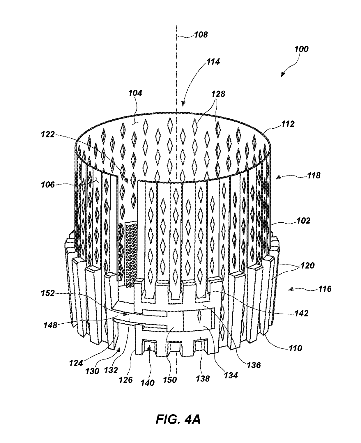
[0084]A core catcher for a coring tool comprising a sleeve comprising a longitudinal axis and at least one slit extending at least partially along a height of the sleeve between an upper end and a lower end thereof. The at least one slit separates a first side surface and a second side surface of the sleeve, wherein the first side surface is located a first distance from the longitudinal axis and the second side surface is located a second distance from the longitudinal axis. Each of the first distance and the second distance measured in a direction transverse to the longitudinal axis. The core catcher also comprises a bridging element extending at least partially about a perimeter of the sleeve. The bridging element operatively couples movement of the first side surface and the second side surface to limit a difference between the first distance and the second distance as a width of the at least one slit that separates the first side surface and the second side surface increases or...

embodiment 2

[0085]The core catcher of Embodiment 1, wherein the bridging element operatively couples movement of the first side surface and the second side surface such that the difference between the first distance and the second distance is less than a thickness of the sleeve as the width of the at least one slit increases or decreases, wherein the thickness measured between an inner surface and an outer surface of the sleeve.

embodiment 3

[0086]The core catcher of either of Embodiments 1 or 2, wherein the bridging element operatively couples movement of the first side surface and the second side surface such that the difference between the first distance and the second distance is substantially zero as the width of the at least one slit increases or decreases.


PUM


Abstract

A core catcher for a coring tool comprises a sleeve comprising a longitudinal axis and at least one slit extending at least partially along a height of the sleeve between an upper end and a lower end thereof. The at least one slit separates a first side surface and a second side surface of the sleeve. The first and second side surfaces are located a first distance and a second distance from the longitudinal axis, respectively, measured in a direction transverse to the longitudinal axis. The core catcher further comprises a bridging element extending at least partially about a sleeve perimeter. The bridging element operatively couples movement of the first side surface and the second side surface to limit a difference between the first and second distances as a width of the at least one slit that separates the first side surface and the second side surface increases or decreases.

Description

TECHNICAL FIELD[0001]The present disclosure, in various embodiments, relates generally to core catchers for coring tools and methods of forming the core catcher. More particularly, the present disclosure relates to core catchers including features configured to couple axial and / or radial movement of a sleeve of the core catcher and to inhibit distortion of the core catcher that may result in loss of a core of subterranean formation material therefrom.BACKGROUND[0002]Formation coring is a well-known process in the oil and gas industry. In conventional coring operations, a core barrel assembly is used to cut a core from the subterranean formation and to transport the core to the surface for analysis. Analysis of the core can reveal invaluable data concerning subsurface geological formations—including parameters such as permeability, porosity, and fluid saturation—that are useful in the exploration for and production of petroleum, natural gas, and minerals. Such data may also be useful...

Claims


Application Information

Patent Timeline
Patent Type & Authority Applications(United States)
IPC IPC(8): E21B25/10
CPCE21B25/10E21B10/02E21B10/605E21B25/00
Inventor KORDEX, PHILUHLENBERG, THOMASWESEMEIER, CHRISTOPH
Owner BAKER HUGHES OILFIELD OPERATIONS LLC
Why Eureka
Try Eureka