
Apparatus, system, and method for catching a core

a core and apparatus technology, applied in cutting machines, transportation and packaging, borehole/well accessories, etc., can solve the problems of large risks in grappling with the cores, material being cut from the substrate can be extremely massive, and the risk of damage or harm can be great, so as to reduce the amount of direct human contact and reduce the risk of damage or harm

Inactive Publication Date: 2009-09-17
IZATT TONY
View PDF6 Cites 6 Cited by
  • Summary
  • Abstract
  • Description
  • Claims
  • Application Information

AI Technical Summary

Benefits of technology

[0006]From the foregoing discussion, it should be apparent that a need exists for an apparatus, system, and method that inhibits free fall of cores from a core bit once they have been severed from a substrate. There is a need to reduce the amount of direct human contact with the core during catching of the core. Beneficially, such an apparatus, system, and method would reduce the risk of damage or harm caused by falling cores.

Problems solved by technology

Hence, the material being cut from the substrate can be extremely massive.
Dealing with these massive cores once they have been severed from the substrate can be challenging.
With moderate to extremely massive cores, the risks in grappling with the cores become great.

Method used


Image

  • Apparatus, system, and method for catching a core
  • Apparatus, system, and method for catching a core
  • Apparatus, system, and method for catching a core

Examples


Embodiment Construction

[0022]Reference throughout this specification to “one embodiment,”“an embodiment,” or similar language means that a particular feature, structure, or characteristic described in connection with the embodiment is included in at least one embodiment of the present invention. Thus, appearances of the phrases “in one embodiment,”“in an embodiment,” and similar language throughout this specification may, but do not necessarily, all refer to the same embodiment.

[0023]Furthermore, the described features, structures, or characteristics of the invention may be combined in any suitable manner in one or more embodiments. In the following description, numerous specific details are provided, such as examples of programming, software modules, user selections, network transactions, database queries, database structures, hardware modules, hardware circuits, hardware chips, etc., to provide a thorough understanding of embodiments of the invention. One skilled in the relevant art will recognize, howe...


PUM


Abstract

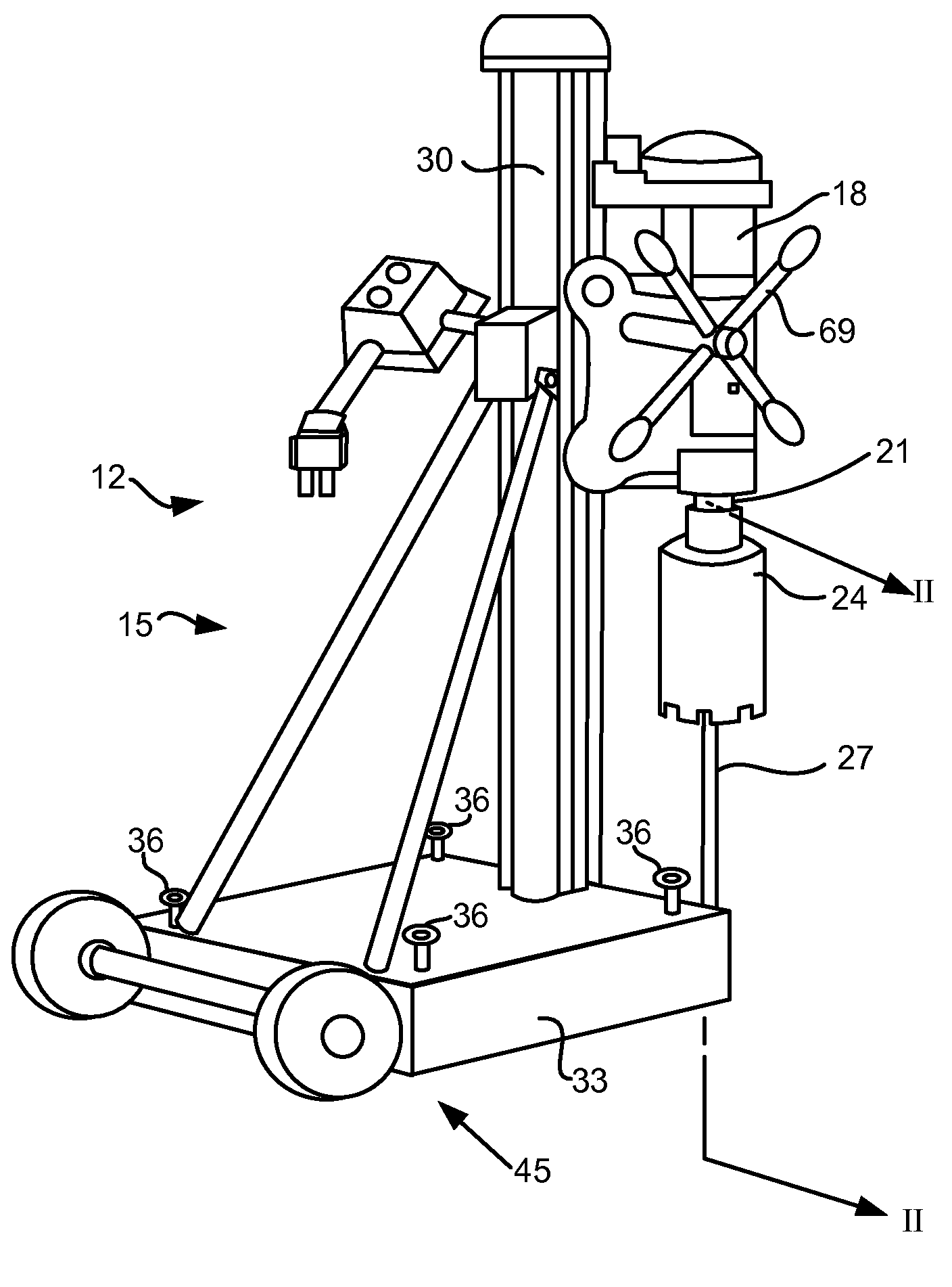
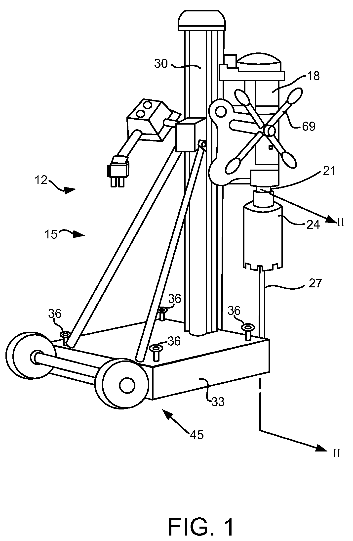
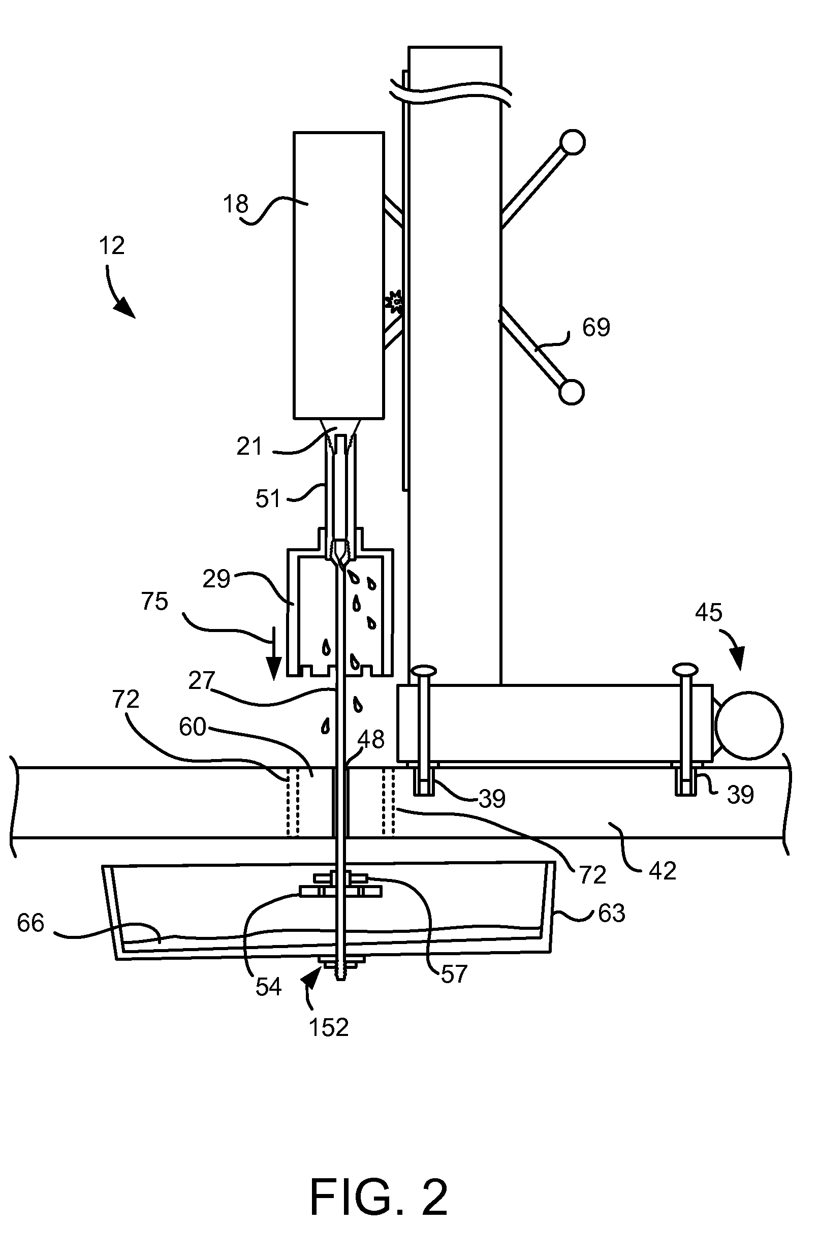
A core catcher includes a catcher rod removably attachable to a core drill. The catcher rod is inserted through a pilot hole in a substrate from which a core is to be removed. A catching element is removably attachable such as by clamping the catching element to a distal end of the catcher rod on an underside of the substrate. A bearing may be disposed between the catching element and the substrate. When severed from the substrate, the core falls only a short distance along the catcher rod and comes to rest on the bearing and the catching element. Thus, the core is inhibited from falling to a floor or ground below the substrate. A bucket may also be supported on the distal end of the catcher rod in order to collect cutting fluid.

Description

BACKGROUND OF THE INVENTION[0001]1. Field of the Invention[0002]This invention relates to core cutting machines and more particularly relates to an apparatus, system, and method for catching cores severed from substrates during core cutting.[0003]2. Description of the Related Art[0004]Core cutting machines are used extensively for creating openings through substrates such as walls or floors in buildings or other structures. These openings provide passageways for ducting, electrical lines, or plumbing, for example. Core cutting machines typically include a core drill, and one or more core bits. A core drill typically has a motor supported on a frame in a form analogous to a drill press. The motor provides rotary action to the core bits. Core cutting machines also have a mechanism for applying a force in an axial direction or in the direction of cutting. Such a mechanism may include a lever arm on a spindle that is configured to move the motor and bit axially along a guide beam of the...

Claims


Application Information

Patent Timeline
Patent Type & Authority Applications(United States)
IPC IPC(8): E21B25/14
CPCB23B51/044
Inventor IZATT, TONY
Owner IZATT TONY
Learn More