Surface Sediment Core Catcher

Active Publication Date: 2015-09-10
THE UNITED STATES OF AMERICA AS REPRESENTED BY THE SECRETARY OF THE NAVY
View PDF2 Cites 6 Cited by
  • Summary
  • Abstract
  • Description
  • Claims
  • Application Information

AI Technical Summary

Benefits of technology

[0003]Described herein is a core catcher comprising: a cap, a cross beam, and a flexible member. The cap is configured to be secured to a first end of a core liner such that when the first end of the core liner is inserted into sediment a sample sediment core enters the core liner through the cap. The cross-beam is coupled to the cap and mounted across the first end of the core liner

Problems solved by technology

These active core catcher designs can also be very bulky, difficult to manufacture because of their many moving parts, and expensive.
Because of their integration with the sampling technologies, t

Method used


Image

  • Surface Sediment Core Catcher
  • Surface Sediment Core Catcher
  • Surface Sediment Core Catcher

Examples


Embodiment Construction

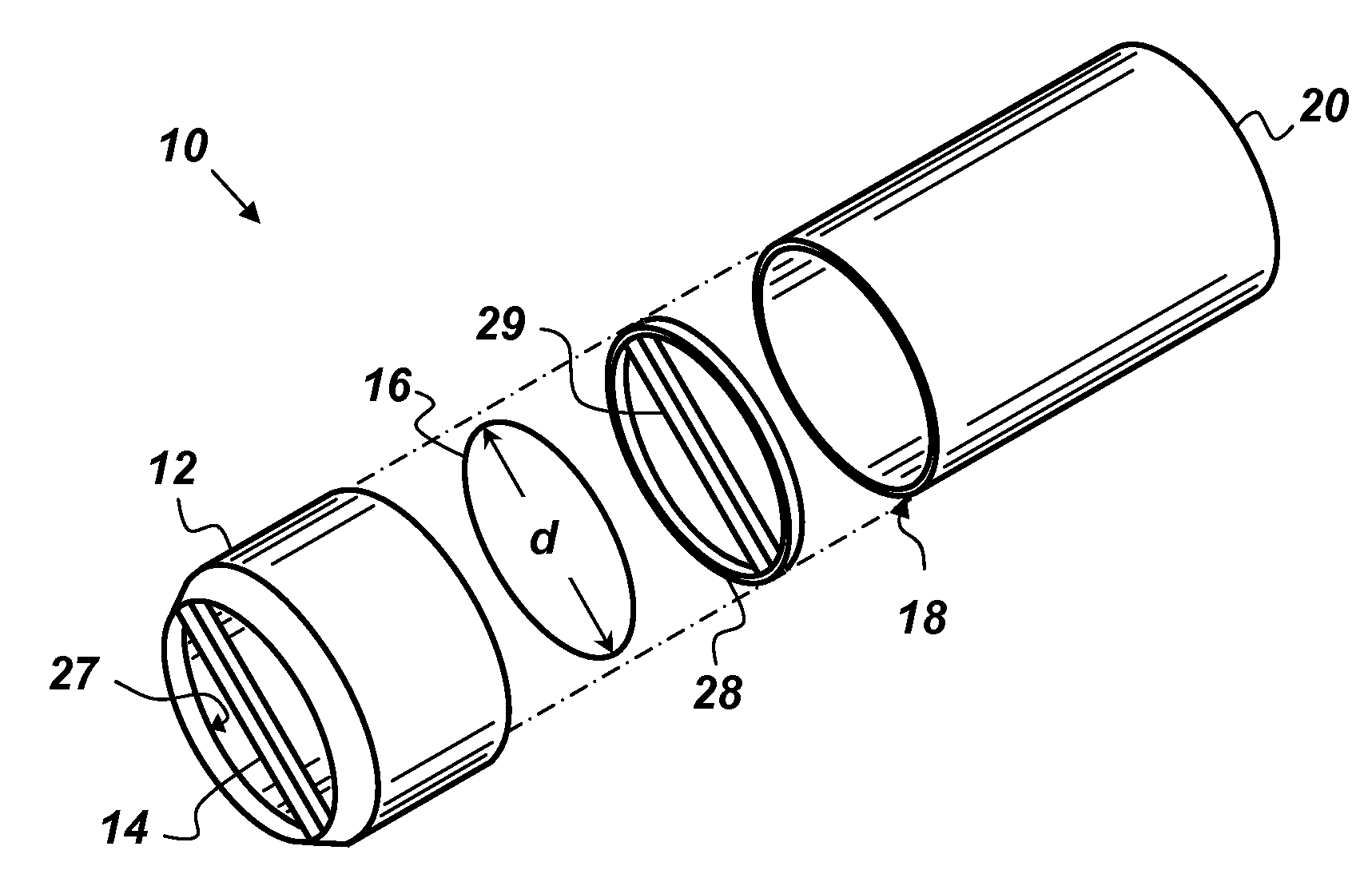
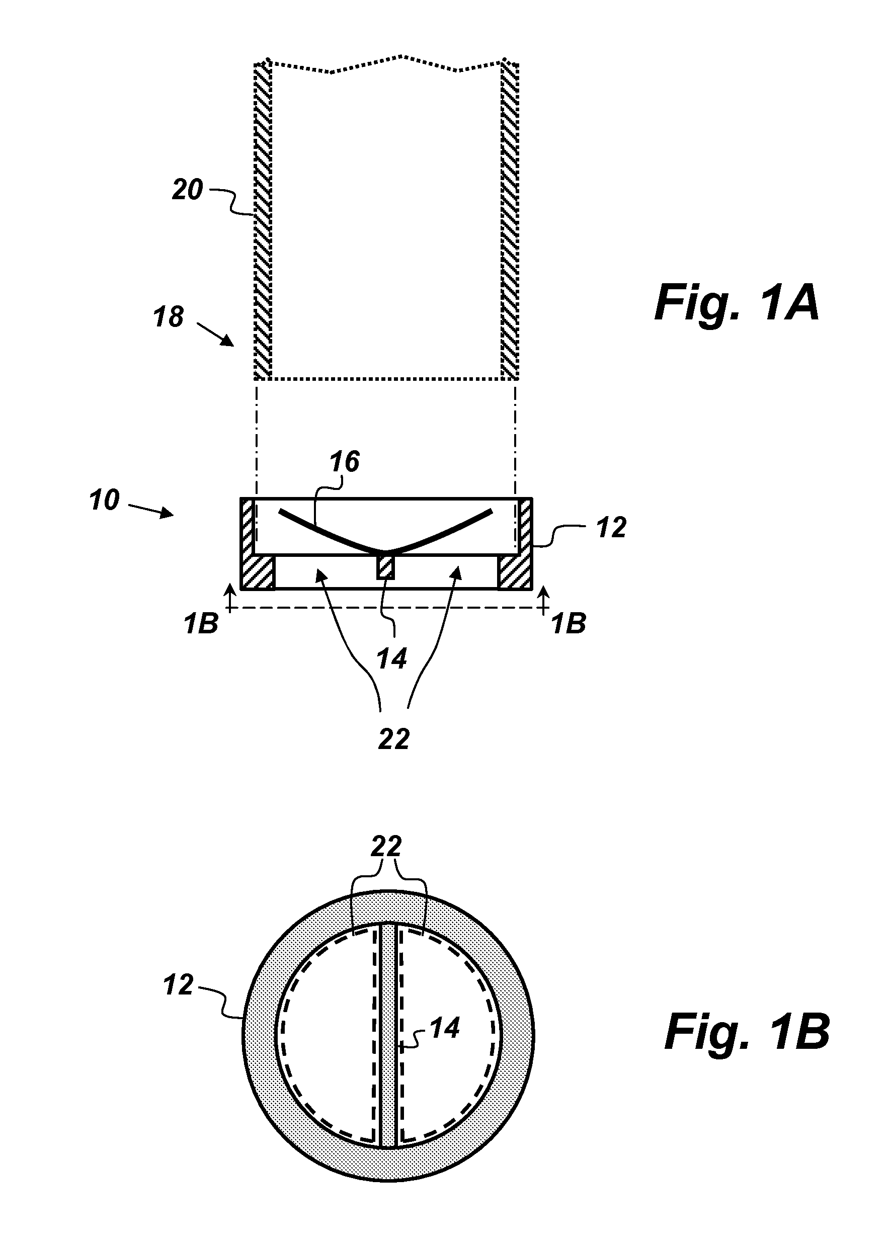
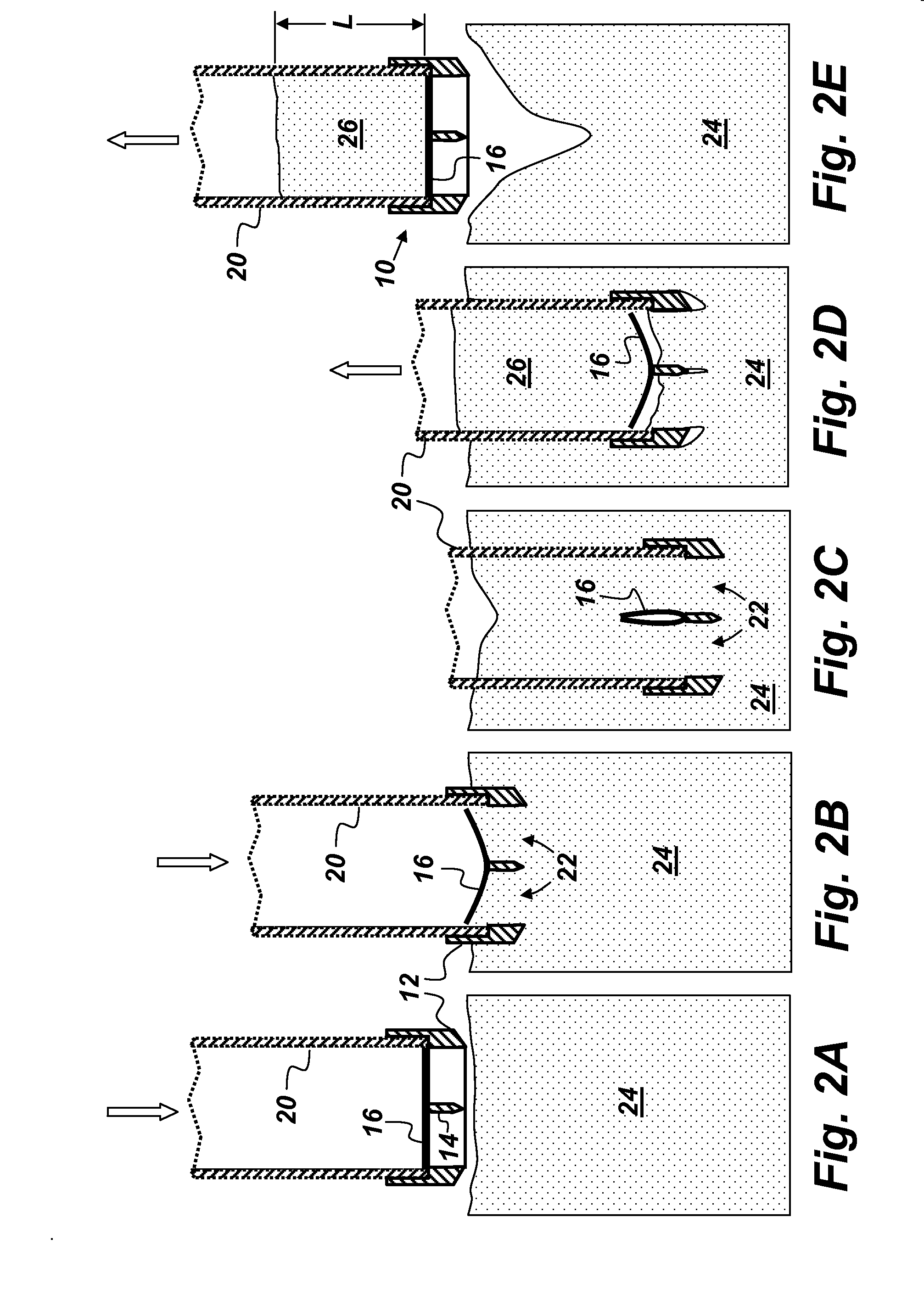
[0013]FIGS. 1A and 1B are illustrations of an embodiment of a surface sediment core catcher 10 comprising, consisting of, or consisting essentially of a cap 12, a cross-beam 14, and a flexible member 16. FIG. 1A is a cross-sectional, side view of the core catcher 10 and FIG. 1B is an end view of the core catcher 10. The cap 12 is configured to be secured to a first end 18 of a core liner 20 such that when the first end 18 of the core liner 20 is inserted into surface sediment a sample sediment core enters the core liner 20 through the cap 12. The cross-beam 14 is coupled to the cap 12 and mounted across the first end 18 of the core liner 20 such that a cross-section of the first end of the core liner 20 is divided into two openings 22. The flexible member 16 is secured to the cross-beam 14 such that the flexible member 16, the cross-beam 14, and the cap 12 form a dual-flap valve. The dual-flap valve is designed to allow a sediment core to enter the core liner 20 through the two open...


PUM


Abstract

A core catcher comprising: a cap configured to be secured to a first end of a core liner such that when the first end of the core liner is inserted into sediment a sample sediment core enters the core liner through the cap; a cross-beam coupled to the cap and mounted across the first end of the core liner such that a cross-section of the first end of the core liner is divided into two openings; a flexible member secured to the cross-beam such that the flexible member, the cross-beam, and the cap form a dual-flap valve designed to allow the sediment core to enter the core liner through the two openings and to prevent the sediment core from escaping the core liner through the cap.

Description

FEDERALLY-SPONSORED RESEARCH AND DEVELOPMENT[0001]The United States Government has ownership rights in this invention. Licensing and technical inquiries may be directed to the Office of Research and Technical Applications, Space and Naval Warfare Systems Center, Pacific, Code 72120, San Diego, Calif., 92152; voice (619) 553-5118; ssc_pac_t2@navy.mil. Reference Navy Case Number 102059.BACKGROUND OF THE INVENTION[0002]There are many types of core catchers in use today. Some core catchers are integrated into core sampling technologies, and require active energy-powered movement to work. These active core catcher designs can also be very bulky, difficult to manufacture because of their many moving parts, and expensive. Because of their integration with the sampling technologies, they cannot function independently. For example, a sphincter-type core catcher is rotated closed by the final movement of a piston in a piston core sampler. Many passive core catchers also exist, the majority of...

Claims


Application Information

Patent Timeline
IPC IPC(8): G21C9/016
CPCG21C9/016Y02E30/30
Inventor ROSEN, GUNTHER H.CHADWICK, DAVID BARTNGUYEN, BRITTNEYNGUYEN, HOA G.BURMEISTER, AARON B.
Owner THE UNITED STATES OF AMERICA AS REPRESENTED BY THE SECRETARY OF THE NAVY
Why Eureka
Try Eureka