Charging connector and method of mounting the same

a charging connector and charging connector technology, applied in the direction of couplings/cases, coupling device connections, electrical devices, etc., can solve the problems of many man hours of replacement, system is not very flexible, and the disassembly of the vehicle-side connector is laborious, etc., to achieve a high degree of freedom for placing and arranging, and the effect of easy formation

Active Publication Date: 2017-03-21
SUMITOMO WIRING SYST LTD
View PDF34 Cites 11 Cited by
  • Summary
  • Abstract
  • Description
  • Claims
  • Application Information

AI Technical Summary

Benefits of technology

[0011]By the fact that there is no fitting portion for fitting the terminal fitting within said housing and the terminal fittings are fitted only within the tower, the tower including the terminal fittings can easily be assembled and disassembled from the vehicle simply by removing the tower from the mating oblong hole provided within the housing. Accordingly, a replacement in case of an electric failure can be performed easily and fast. Moreover, in case of a design change such as a change of the number of the terminals or the size thereof, only the inner design of the tower needs to be changed without changing the housing. Accordingly, no change is required for the opening portion provided in the panel of a vehicle. Further, the cylindrical mounting surface provides a stiff assembly, so that a tilting of the tower mounted within the housing can be avoided.
[0012]Further, due to the two-piece design comprising the housing on one side and the tower including the terminal fittings on the other side, the manufacture and assembly procedure is facilitated. In particular, there are no undercuts which would be difficult to form when forming the connector from resin by insert-molding. Further, the wires of a wiring harness with which the terminal fittings are to be connected are very stiff. Therefore, the two-piece design provides the advantage of an improved and facilitated mounting procedure.
[0015]A sealing may be provided on the terminal fitting in front of a connection portion of the terminal fitting for connecting the terminal fitting with a wire. Accordingly, a barrel portion or connection portion of the terminal fitting is a dry area such that contact corrosion of a crimped connection of the terminal with the wire can be avoided so as to avoid an increase of an electric resistance.
[0019]The tower may comprise at least one drain opening for draining water that may have entered a front side of the connector. The drain opening may be arranged in the exposed portion(s) of the accommodating chamber(s). The fact that water is drained from the tower via the drain openings provided in the exposed portion of the accommodating chamber leads to the advantage that the rear part of the connector is a dry area and there is no need to provide a drain within the vehicle such as a hose for draining water having entered the connector.
[0020]The drain openings may be formed easily due to the two-piece concept of the connector, as there are no undercuts in this case, so that there is a high degree of freedom for placing and arranging the drain openings. Accordingly, the drain openings may be displaced with respect to each other in the radial and / or axial direction.
[0023]According to a particular embodiment, the tower may have a cylindrical shape and the mating hole of the housing may be a cylindrical (oblong) hole. Accordingly, the manufacture of these components can be easily achieved. However, the invention is not limited to such configuration and the tower and the mating hole may also substantially be ellipsoid, square-shaped, rectangular or the like.

Problems solved by technology

When the mounting opening of the vehicle has to be changed due to changing the vehicle-side connector, the system is not very flexible.
Accordingly, when the vehicle-side connector fails and needs to be replaced, the disassembly of the vehicle-side connector is laborious and many man hours are required for replacement.
Further, the wires of a wiring harness with which the terminal fittings are to be connected are very stiff.

Method used


Image

  • Charging connector and method of mounting the same
  • Charging connector and method of mounting the same
  • Charging connector and method of mounting the same

Examples


Embodiment Construction

[0031]Hereinafter, a particular embodiment of the present invention is described with reference to the accompanying drawings. The following embodiment is a specific example of the present invention and does not limit the technical scope of the present invention.

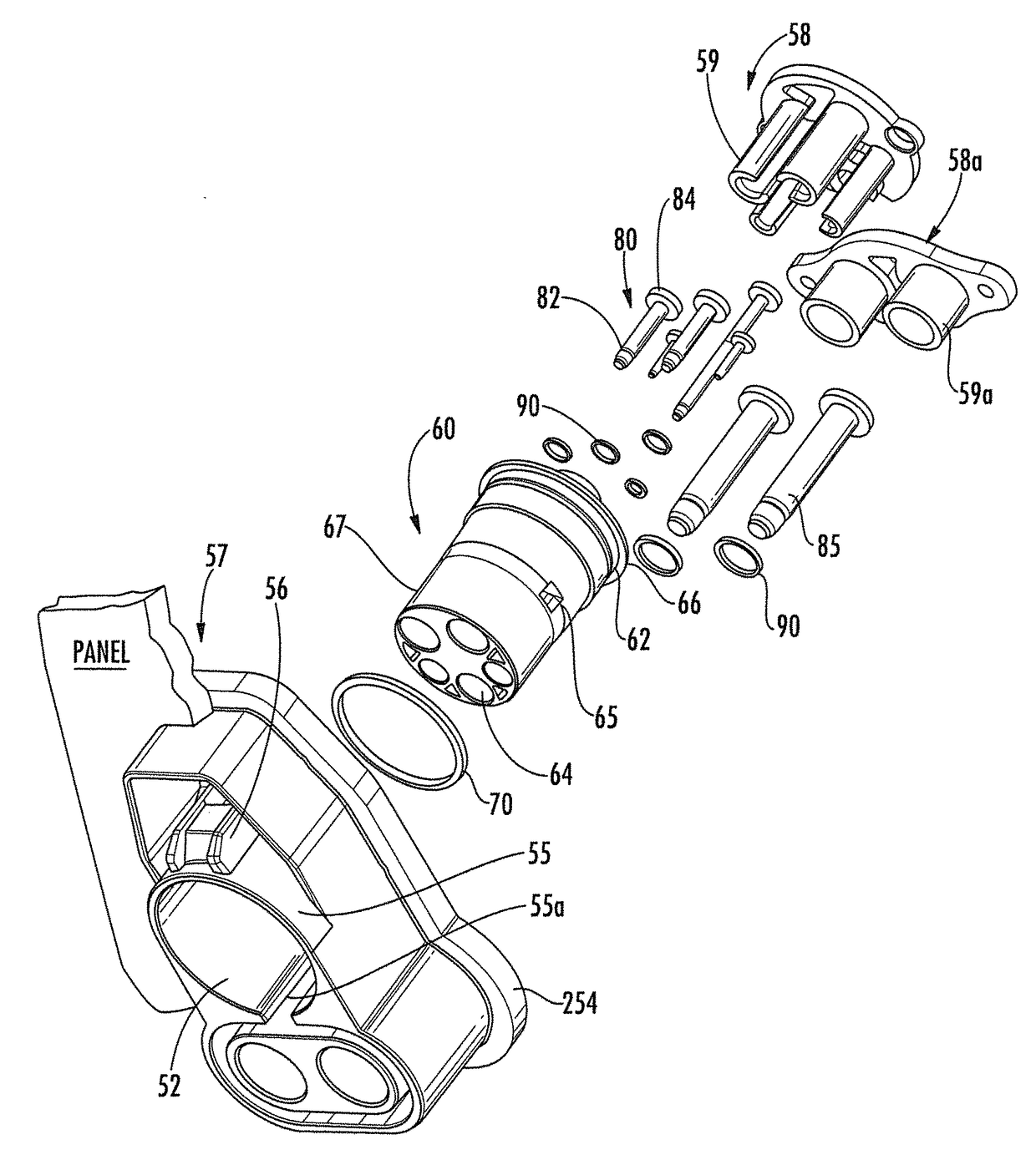
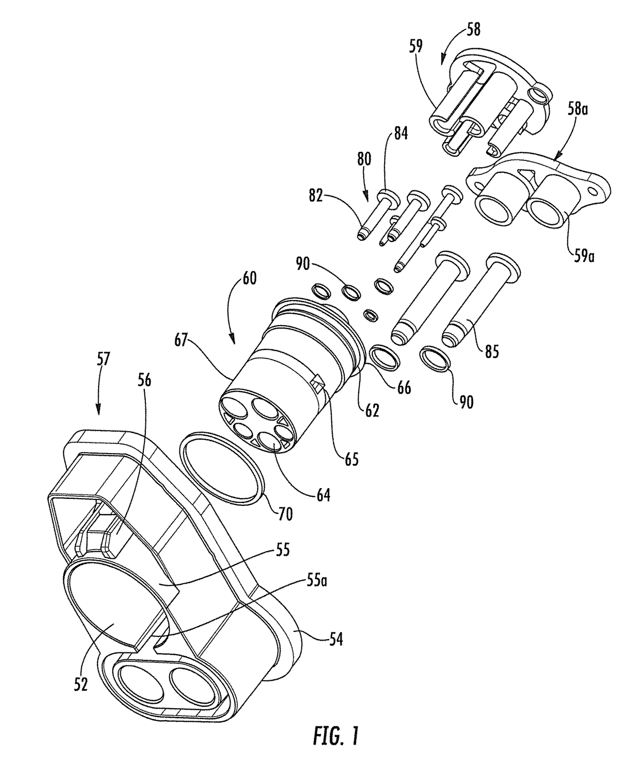
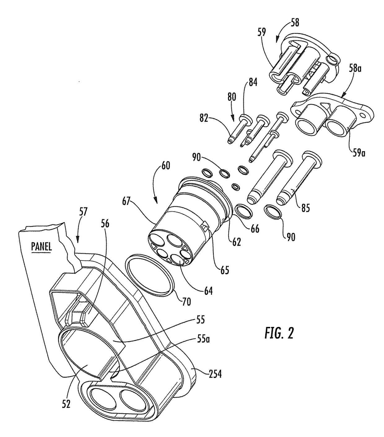
[0032]FIGS. 1 to 3 show a vehicle-side charging connector for an Electric Vehicle (EV) Conductive Charge Coupler according to one particular embodiment.

[0033]As shown in FIG. 1, the vehicle-side charging connector comprises a vehicle-side housing 51 being made e.g. of synthetic resin and / or having a mounting plate 54 to be arranged at an opening edge of a vehicle panel so as to mount the housing 51 of the connector at or in a mounting opening of the vehicle. The mounting plate 54 is preferably provided with a glue or a bonding agent such as Sikaflex® so as to bond and seal the mounting plate 54 to the opening edge of the vehicle panel. Alternatively or additionally, a separate seal may be provided, such as a silicone or rubbe...


PUM


Abstract

A charging connector for charging a battery in a vehicle has a housing (51) mounted to a vehicle. A tower (60) is in the housing (51) and has at least one accommodating chamber (64) for accommodating at least one terminal fitting (80). The tower (60) is inserted into a mating hole (52) of the housing (51). A seal (70) is between the tower (60) and the housing (51). The accommodating chamber (64) has a fitting (64a) at a rear end for fitting the terminal fitting (80) and an exposed portion (64b) at a front end for exposing a leading contact (82) of the terminal fitting (80) to be contacted with a mating terminal fitting of a mating charging connector on a charging cable. The tower (60) can be assembled and disassembled from the housing (51) with the terminal fitting(s) (80) mounted within the accommodating chamber(s) (64) of the tower (60).

Description

BACKGROUND[0001]1. Field of the Invention[0002]The present invention relates to a vehicle-side charging connector to be mounted in a vehicle as well as to a method of mounting the same in a vehicle.[0003]2. Description of the Related Art[0004]Electric cars contribute to cleaner air in cities because they produce no harmful emissions. An electric vehicle (EV) recharged from the US grid electricity in 2008 emits about 115 grams of CO2 per kilometer, whereas a conventional US-market gasoline powered car emits about 250 grams of CO2 per kilometer. The concept “Vehicle to Grid” provides electric cars and hybrid vehicles as energy reservoir for the public power grid. In this concept, vehicles parking most time of their life, may be used as energy source and accumulator so as to compensate for peak loads in the public power grid. This concept however, requires a reliable electric connection of the vehicles with the public power grid, even under wet and hot / cold weather conditions of the pa...

Claims


Application Information

Patent Timeline
Patent Type & Authority Patents(United States)
IPC IPC(8): H01R13/436H01R13/52
CPCH01R13/5202
Inventor SCHMIDT, HEIKO
Owner SUMITOMO WIRING SYST LTD
Why Eureka
Try Eureka