Prediction-based touch contact tracking

a technology of prediction and touch contact, applied in the direction of instruments, computing, electric digital data processing, etc., can solve the problem that the location generated by the signals of the touch screen may have jitters

US9606656B2Active Publication Date: 2017-03-28EGALAX EMPIA TECH INC
10 Cites 3 Cited by

Patent Information

Authority / Receiving Office
US · United States
Patent Type
Patents(United States)
Current Assignee / Owner
Publication Date
2017-03-28

Smart Images

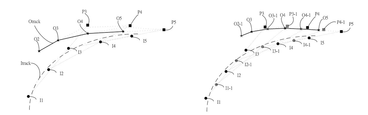
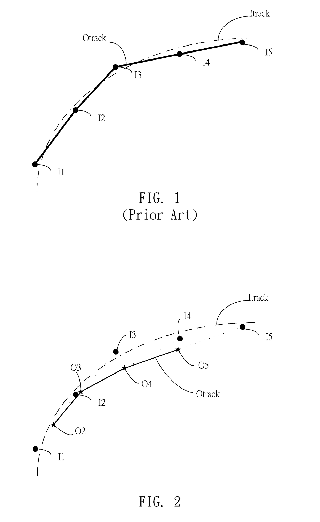
  • Figure 1
    Figure 1
  • Figure 2
    Figure 2
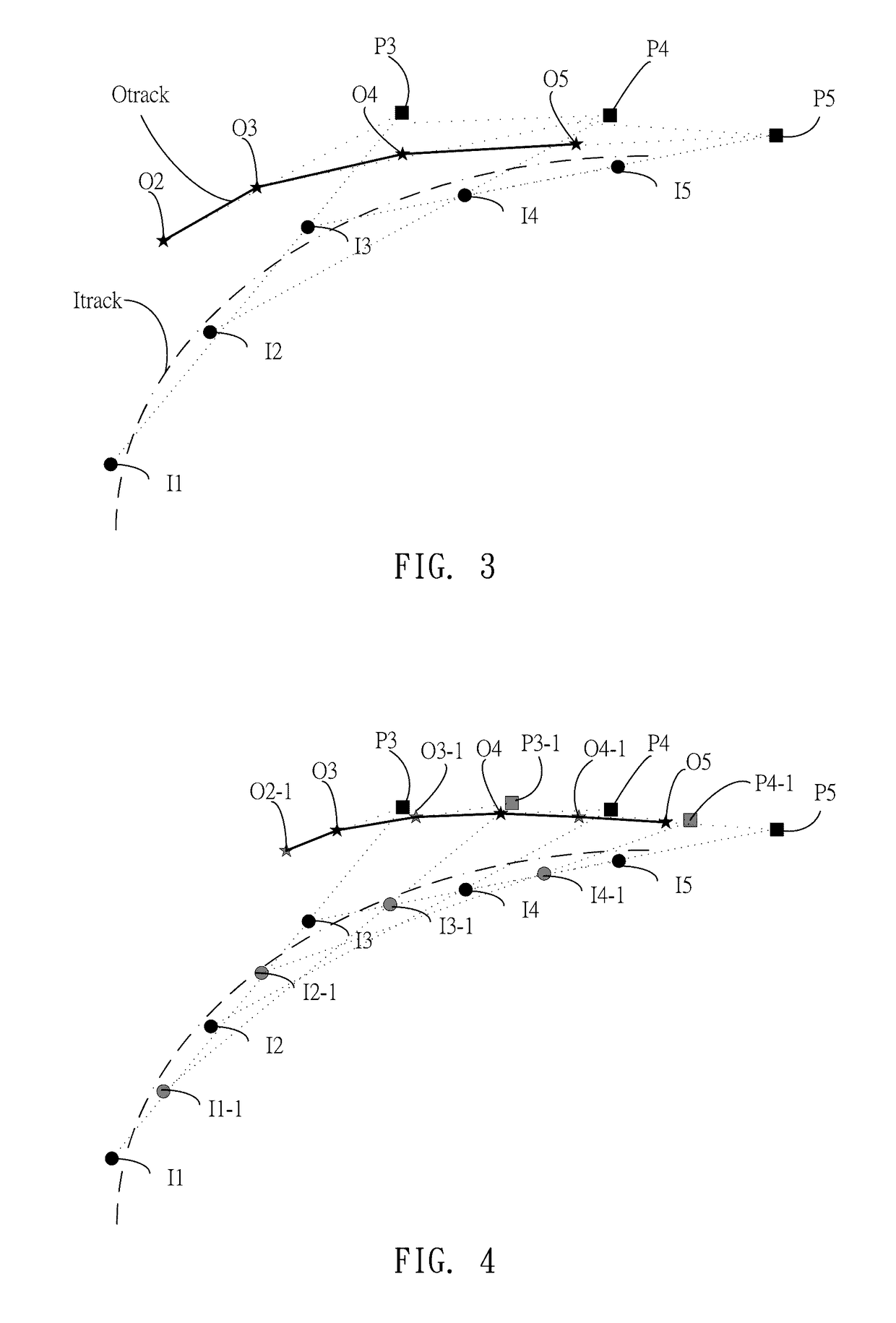
  • Figure 3
    Figure 3
Patent Text Reader

Abstract

When an external object approaches or touches a touch sensor, predicted locations of the external object can be generated by detected locations according to signals from the touch sensor. The latest predicted location is shifted backwards towards the latest reported location for a portion of the distance between the predicted location and the latest reported location to generate a new reported location, whereby jittering of the reported locations caused by noise in the signals of the touch sensor can be reduced or filtered.
Need to check novelty before this filing date? Find Prior Art

Description

CROSS REFERENCE TO RELATED APPLICATIONS

[0001] This application claims the benefit of U.S. Provisional Application No. 61 / 702,301, filed on Sep. 18, 2012, which are herein incorporated by reference for all intents and purposes.BACKGROUND OF THE INVENTION

[0002] 1. Field of the Invention

[0003] The present invention relates to a touch contact tracking method, and more particularly, to a prediction-based touch contact tracking method.

[0004] 2. Description of the Prior Art

[0005] When an external conductive object touches or approaches a touch screen, the touch screen will detect the location of the external conductive object. Since the touch screen may be affected by noise interference, the detected location of the external conductive object may have certain offset. Referring to FIG. 1, an input track Itrack is the track of an external conductive object moving on a touch screen, and an output track Otrack is the track detected by the touch screen. The output track Otrack may have the jitter ph...

Examples

Embodiment Construction

[0017]Some embodiments of the present invention are described in details below. However, in addition to the descriptions given below, the present invention can be applicable to other embodiments, and the scope of the present invention is not limited by such, rather by the scope of the claims. Moreover, for better understanding and clarity of the description, some components in the drawings may not necessary be drawn to scale, in which some may be exaggerated relative to others, and irrelevant parts are omitted.

[0018]In order to overcome the prior-art issues, a filtering process is usually employed to reduce or filter out the jittering problem as mentioned before. Referring to FIG. 2, a new reported location can be determined by performing interpolation between the latest reported location (the last reported location) and the latest detected location (the current detected location) with a certain ratio. For example, the touch screen sequentially detects reported locations I1, I2, . ....