Mill-Through Tailpipe Liner Exit

a technology of tailpipe liner and milling machine, which is applied in the direction of directional drilling, foundation engineering, artificial islands, etc., can solve the problems of reducing the profitability of additional lateral drilling, the difficulty of drilling precisely on target, and the cost of drill rigs, so as to reduce the distance between the heel and the formation. , the effect of safe running

Active Publication Date: 2010-06-17
CONOCOPHILLIPS CO
View PDF12 Cites 2 Cited by
  • Summary
  • Abstract
  • Description
  • Claims
  • Application Information

AI Technical Summary

Benefits of technology

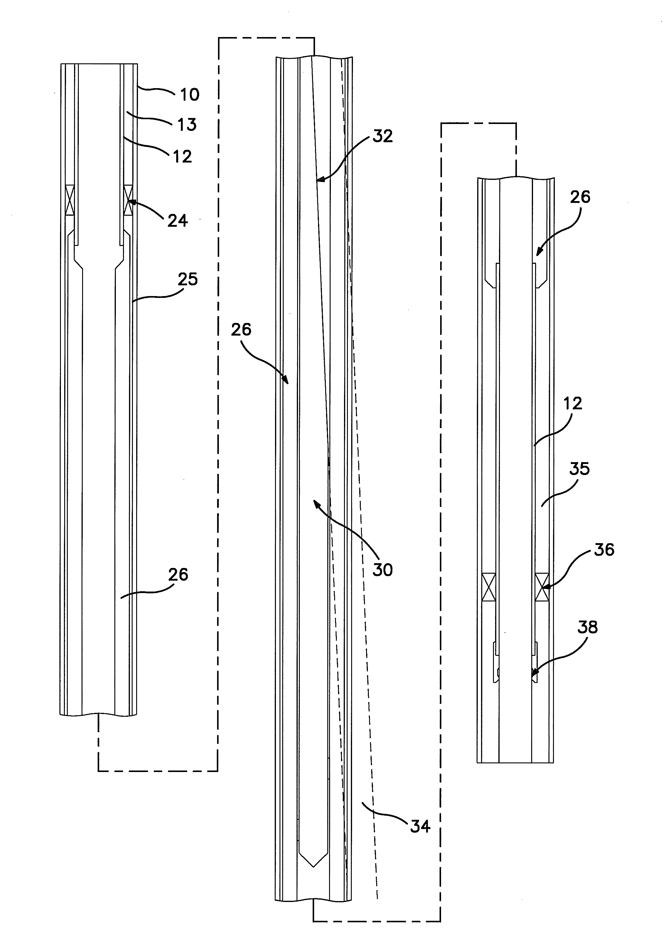
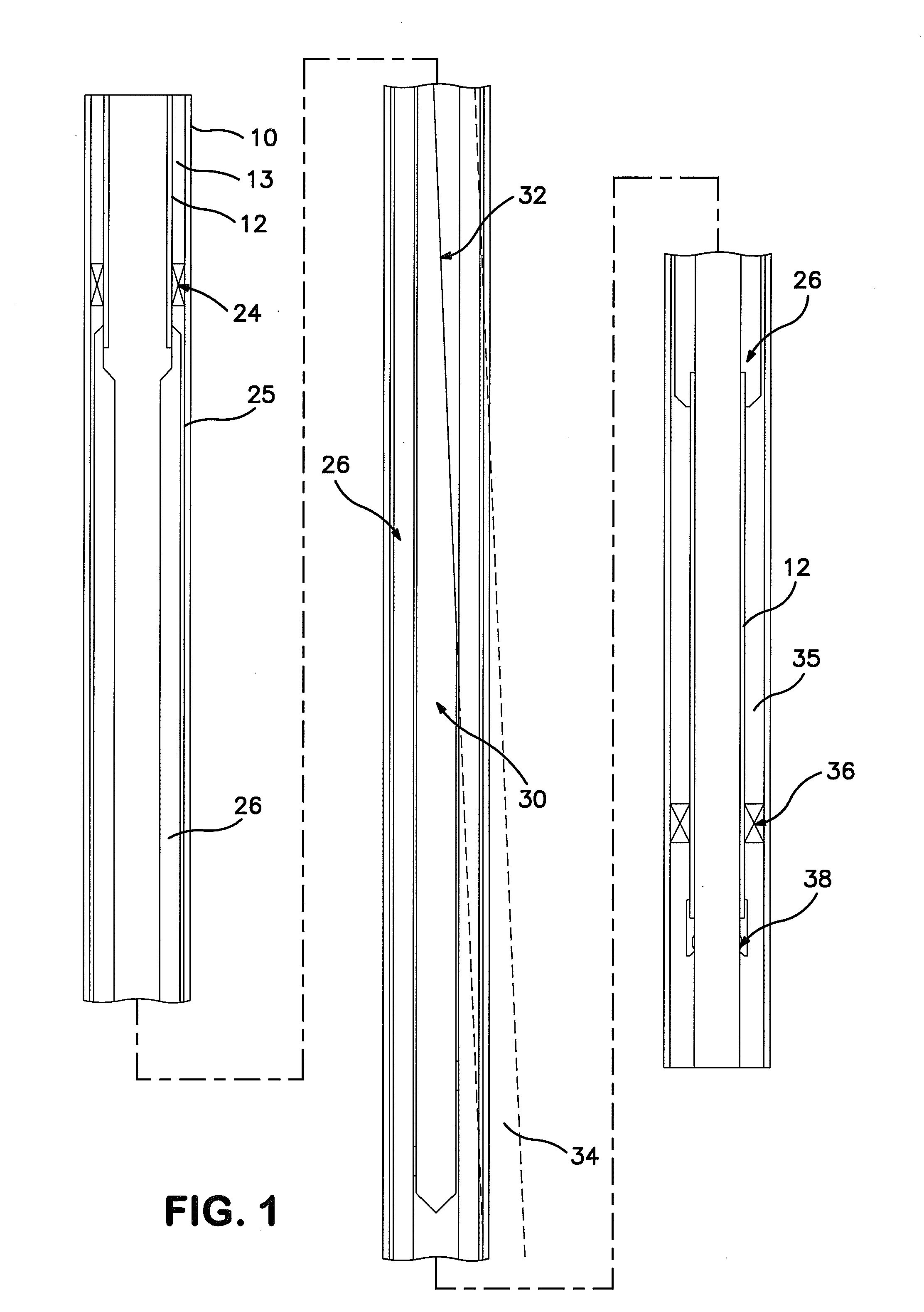
[0010]In an embodiment of the present invention, a process for drilling a sidetrack wellbore into a desired formation, wherein the process includes: (a) installing a liner within the formation, wherein the liner includes an outer diameter and an inner diameter; (b) installing a tubing string within the formation, wherein the tubing string includes an inner diameter and an outer diameter; (c) installing a tailpipe releasably attached to the tubing string, wherein the tailpipe includes an inner diameter and an outer diameter, wherein the tailpipe is positioned within the liner with the use of millable stabilizing bands, wherein the millable stabilizing bands are connected to the outer diameter of the tailpipe, wherein the outer diameter of the tailpipe is increased until the clearance between the tailpipe and the liner can be safely run into the formation, wherein a diametrical clearance between the tailpipe and the liner is between about ⅛ inch to about ¼ inch, wherein the inner diameter of the tailpipe is larger than the inner diameter of the liner, wherein the tailpipe is fabricated from a durable material capable of being milled; (d) installing a packer assembly, wherein the packer assembly is located along the tubing string and above the tailpipe; (e) installing a whipstock assembly, wherein the whipstock assembly includes an inclined guide surface, wherein the whipstock assembly includes a heel, wherein the tailpipe positions the whipstock assembly near a centerline within the liner, wherein the difference between the inner diameter of the liner and the maximum deviation of the whipstock from the centerline in the formation is minimized to about ½ the value of the diametrical clearance, thereby reducing the distance between the heel of the whipstock to the inner wall of the liner, wherein the whipstock assembly is guided into the formation to a desired location within the tailpipe, wherein the whipstock assembly is then set in place at the desired location within the tailpipe; (f) guiding a milling assembly into the formation through the tailpipe and onto the inclined guide surface of the whipstock assembly, wherein the milling assembly is a straight motor mill; and (g) milling through the tailpipe and the liner in a single milling operation.
[0011]In a further embodiment of the present invention, a process for drilling a sidetrack wellbore into a desired formation, wherein the process includes: (a) installing a liner within the formation, wherein the liner includes an outer diameter and an inner diameter; (b) installing a tubing string within the formation, wherein the tubing string includes an inner diameter and an outer diameter; (c) installing a tailpipe releasably attached to the tubing string, wherein the tailpipe includes an inner diameter and an outer diameter, wherein the outer diameter of the tailpipe is increased until the clearance between the tailpipe and the liner can be safely run into the formation; (d) installing a whipstock assembly, wherein the whipstock assembly includes an inclined guide surface, wherein the whipstock assembly includes a heel, wherein the tailpipe positions the whipstock assembly near a centerline within the liner, wherein the difference between the inner diameter of the liner and the maximum deviation of the whipstock from the centerline in the formation is minimized to less than the value of the diametrical clearance, thereby reducing the distance between the heel of the whipstock to the inner wall of the liner, wherein the whipstock assembly is guided into the formation to a desired location within the tailpipe, wherein the whipstock assembly is then set in place at the desired location within the tailpipe; (e) guiding a milling assembly into the formation through the tailpipe and onto the inclined guide surface of the whipstock assembly; and (f) milling through the tailpipe and the liner.
[0012]In another embodiment of the present invention, a system for drilling a sidetrack wellbore into a desired formation, wherein the system includes: (a) a liner within the formation, wherein the liner includes an outer diameter and an inner diameter; (b) a tubing string within the formation, wherein the tubing string includes an inner diameter and an outer diameter; (c) a tailpipe releasably attached to the tubing string, wherein the tailpipe includes an inner diameter and an outer diameter, wherein the outer diameter of the tailpipe is increased until the clearance between the tailpipe and the liner can be safely run into the formation; (d) a whipstock assembly, wherein the whipstock assembly includes an inclined guide surface, wherein the whipstock assembly includes a heel, wherein the tailpipe positions the whipstock assembly near a centerline within the liner, wherein the difference between the inner diameter of the liner and the maximum deviation of the whipstock from the centerline is minimized to about ½ the value of the diametrical clearance, thereby reducing the distance between the heel of the whipstock to the inner wall of the liner; and (e) a milling assembly into the formation through the tailpipe and onto the inclined guide surface of the whipstock assembly, wherein the milling assembly mills through the tailpipe and the liner.

Problems solved by technology

However, the ability to drill precisely on target is a significant challenge when drilling laterals.
Drill rigs are expensive and several extra days of rig time may substantially reduce the profitability of drilling additional laterals.
However, the use of kickoff plugs may be problematic due to the fact that the plug prevents access to further production fluids from lower portions of the original wellbore because the cement seals the well at the deviation.
However, when the clearance between the tailpipe and the liner approach the diameter of the mill, the mill cannot cut through the liner but rather mills down the annulus potentially trapping the mill.
Additionally, cementing operations utilized in current methods of high ratio window exits severely restrict access to lower formations, requiring expensive and risky operations to gain access to these lower formations.

Method used


Image

  • Mill-Through Tailpipe Liner Exit
  • Mill-Through Tailpipe Liner Exit

Examples


Embodiment Construction

[0015]Reference will now be made in detail to embodiments of the invention, one or more examples of which are illustrated in the accompanying drawings. Each example is provided by way of explanation of the invention, not as a limitation of the invention. It will be apparent to those skilled in the art that various modifications and variations can be made in the present invention without departing from the scope or spirit of the invention. For instances, features illustrated or described as part of one embodiment can be used in another embodiment to yield a still further embodiment. Thus, it is intended that the present invention cover such modifications and variations that come within the scope of the appended claims and their equivalents.

[0016]In the description which follows, like parts are marked throughout the specification and drawing with the same reference numerals. The drawing figures are not necessarily to scale and certain features are shown in schematic form or are exagge...


PUM


Abstract

A method and apparatus for forming a window in the wall of a tubular wellbore. In one embodiment described herein, a down hole apparatus for forming a window in the wall of a wellbore utilizing a plurality of tubing string sections and a thick tailpipe positioned at the down hole end of a tubing section.

Description

CROSS-REFERENCE TO RELATED APPLICATIONS[0001]This application claims priority benefit under 35 U.S.C. Section 119(e) to U.S. Provisional Patent Ser. No. 61 / 121,789 filed on Dec. 11, 2008, the entire disclosure of which is incorporated herein by reference.FIELD OF THE INVENTION[0002]Embodiments of the present invention relate to a process and a system for drilling sidetrack wells. Specifically, the present invention relates to the drilling of sidetrack wells in existing casing strings which are in close proximity to the packer assembly and / or contain a large constriction ratio.BACKGROUND OF THE INVENTION[0003]It is well known that hydrocarbons may be produced from subterranean formations through a well that has been drilled into a hydrocarbon bearing formation. Drilling is accomplished by utilizing a drill bit mounted to the end of a drill support member, i.e., a drill string. The drill string is rotated by a top drive, i.e., rotary table, on a surface platform or by a down hole moto...

Claims


Application Information

Patent Timeline
Patent Type & Authority Applications(United States)
IPC IPC(8): E21B7/04
CPCE21B7/061
Inventor HEARN, DAVID D.GANTT, LAMAR L.GOBER, HOWARD
Owner CONOCOPHILLIPS CO
Why Eureka
Try Eureka