Steam turbine system and method for starting steam turbine

Active Publication Date: 2019-09-26
MITSUBISHI HEAVY INDUSTIES COMPRESSOR CORP
View PDF0 Cites 3 Cited by
  • Summary
  • Abstract
  • Description
  • Claims
  • Application Information

AI Technical Summary

Benefits of technology

[0027]According to the invention, it is possible

Problems solved by technology

Specifically, in the steam turbine, leak of air into the casing is limited when t

Method used


Image

  • Steam turbine system and method for starting steam turbine
  • Steam turbine system and method for starting steam turbine
  • Steam turbine system and method for starting steam turbine

Examples


Embodiment Construction

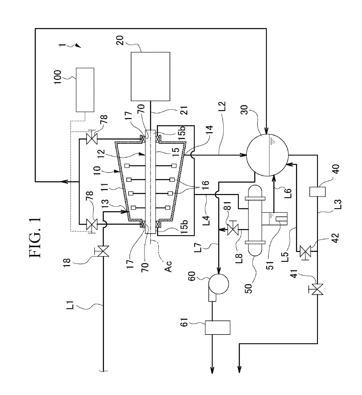
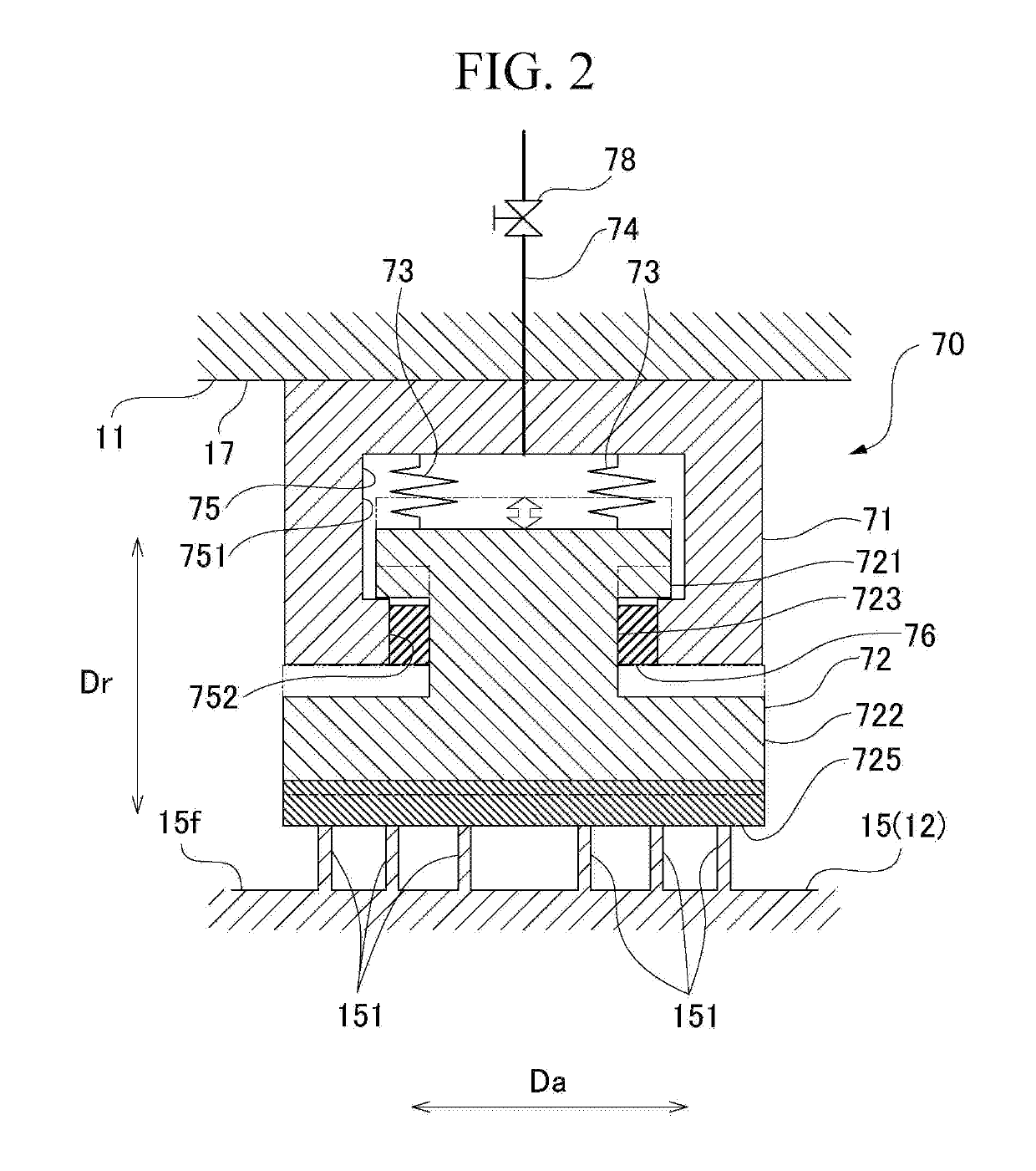
[0031]Hereinafter, a steam turbine, a steam turbine system, and a method for starting a steam turbine in the invention will be described with reference to the drawing. FIG. 1 is a view showing a schematic configuration of the steam turbine system in the embodiment of the invention. FIG. 2 is a sectional view showing a shaft sealing device provided in the steam turbine of the steam turbine system.

[0032]As shown in FIG. 1, a steam turbine system 1 includes a steam turbine 10, a compressor 20, a condenser 30, a condensate pump 40, a deaerator 50, a vacuum pump 60, and a control device 100.

[0033]The steam turbine 10 includes a casing 11 and a rotor 12. Steam is fed into the casing 11 from the outside. The casing 11 has a tubular shape extending in an axial direction Da in which a central axis Ac of the rotor 12 extends. The casing11 has a steam inlet 13 provided on a first side in the axial direction Da, and a steam outlet 14 provided on a second side in the axial direction Da. A steam ...


PUM


Abstract

A steam turbine system includes: a steam turbine having a casing into which steam is fed from an outside of the casing and a rotating shaft that is provided within the casing so as to be rotatable around a central axis; a deaerator that is connected to the steam turbine and that deaerates leaked steam that has leaked from a gap between the casing and the rotating shaft to the outside of the casing; a vacuum pump that is connected to the deaerator and that lowers a pressure within the deaerator; and a shaft sealing device that is connected to the deaerator and that seals the gap between the casing and the rotating shaft. The shaft sealing device has a seal member having a seal body, a housing, a biasing member, and a negative-pressure introduction part.

Description

TECHNICAL FIELD[0001]The present invention relates to a steam turbine system and a method for starting a steam turbine.BACKGROUND ART[0002]In order to drive compressors, generators, or the like, steam turbines may be used. The steam turbines include a casing and a rotor. The rotor includes a rotating shaft that is rotatably supported by the casing, and turbine blades that are provided integrally with the rotating shaft. At least an output-side end part of the rotating shaft protrudes outward through the casing. In such steam turbines, the rotor is rotated by causing steam fed into the casing from the outside to collide against the turbine blades. A driving target is driven by transmitting the rotation of the rotor to the driving target via the end part of the rotating shaft that protrudes to the outside of the casing.[0003]Steam turbine systems for which such steam turbines are used are provided with a condenser that condenses the steam discharged from a steam turbine, and a ground ...

Claims


Application Information

Patent Timeline
IPC IPC(8): F01D11/02F02C7/28
CPCF05D2260/6022F02C7/28F16J15/3452F01D11/025F05D2240/59F16J15/346F01D11/04F01K7/16F01K11/02F01D11/003F01D11/06F01D19/00F05D2240/63
Inventor NOGAMI, TOMOAKIKODA, TAKURO
Owner MITSUBISHI HEAVY INDUSTIES COMPRESSOR CORP
Why Eureka
Try Eureka