

Cutting fluid tank for machine tool
- Summary
- Abstract
- Description
- Claims
- Application Information
AI Technical Summary
Benefits of technology
Problems solved by technology
Method used
Image

Examples
Embodiment Construction
[0026]The embodiments of the present invention will be described below with reference to FIG. 1 to FIG. 3.
[0027]In the following description, the lower side and the upper side of FIG. 1 are referred to as front and rear, respectively. Likewise, the left and right sides of FIG. 1 are referred to as left and right, respectively.
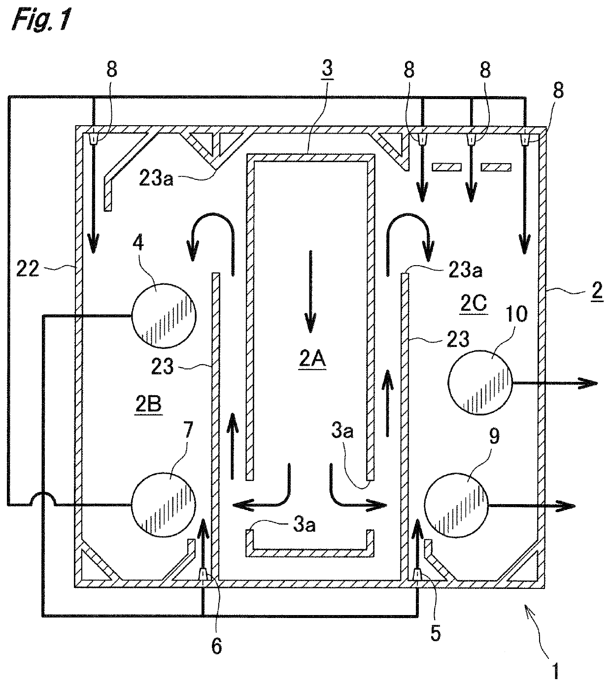
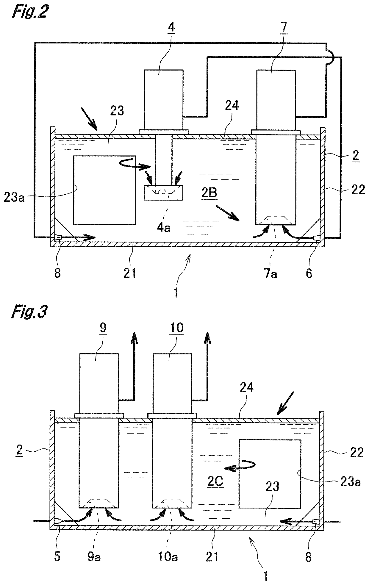
[0028]A cutting fluid tank 1 of a machine tool, in accordance with the present embodiment includes a tank main body 2 in which a sludge-containing cutting fluid that is discharged from a processing region (not shown) of the machine tool flows in through inflow points 3a and is stored.
[0029]The tank main body 2 has a bottom wall 21 that is substantially rectangular in plan view, and a peripheral wall 22 that is vertically extending upward from a peripheral edge of the bottom wall 21. The tank main body 2 is provided at a middle portion in a left-right width direction thereof with a chip conveyor 3 that is elongated in the front-rear direction. The chip conveyor ...
PUM
| Property | Measurement | Unit |
|---|---|---|
| Flow rate | aaaaa | aaaaa |
Abstract
Description
Claims
Application Information