Method of driving plasma display panel

a plasma display panel and plasma technology, applied in the direction of instruments, static indicating devices, etc., can solve the problems of low driving efficiency and reduced driving efficiency of pdp applying such a driving waveform

Inactive Publication Date: 2006-04-20
LG ELECTRONICS INC
View PDF3 Cites 5 Cited by
  • Summary
  • Abstract
  • Description
  • Claims
  • Application Information

AI Technical Summary

Benefits of technology

[0034] According to the present invention, there is provided with a method of driving a plasma display panel including a sustain electrode, an address electrode and a scan electrode based on a non-discharge area defined on the coordinates having X, Y and Z axes and a discharge area defined at exterior of the non-discharge area, wherein the Z axis represents the voltage applied to the sustain electrode, the X axis crossing the Z axis represents a voltage applied to the address electrode, and the Y axis passes through a point of cross of both the Z axis and the X axis and exists at a first quarter-face and a third quarter-face of an orthogonal coordinates formed of the Z axis and the X axis, comprising: applying a negative first voltage to the sustain electrode for the sustaining period to move a wall voltage of an on cell existed at a first initialization location of the non-discharge area to a first location of the discharge area; maintaining a voltage of the sustain electrode and inducing an ac

Problems solved by technology

However, the PDP applying such a driving waveform has a disadvantage of a low driving efficiency in a panel having an opposition discharge of a low condition in characteristics such as a secondary electron emission coefficient of MgO protective film, a composition of MgO protective film, a d

Method used


Image

  • Method of driving plasma display panel
  • Method of driving plasma display panel
  • Method of driving plasma display panel

Examples


Embodiment Construction

[0055] Reference will now be made in detail to the preferred embodiments of the present invention, examples of which are illustrated in the accompanying drawings.

[0056] Hereinafter, the preferred embodiments of the present invention will be described in detail with reference to FIGS. 10 to 20.

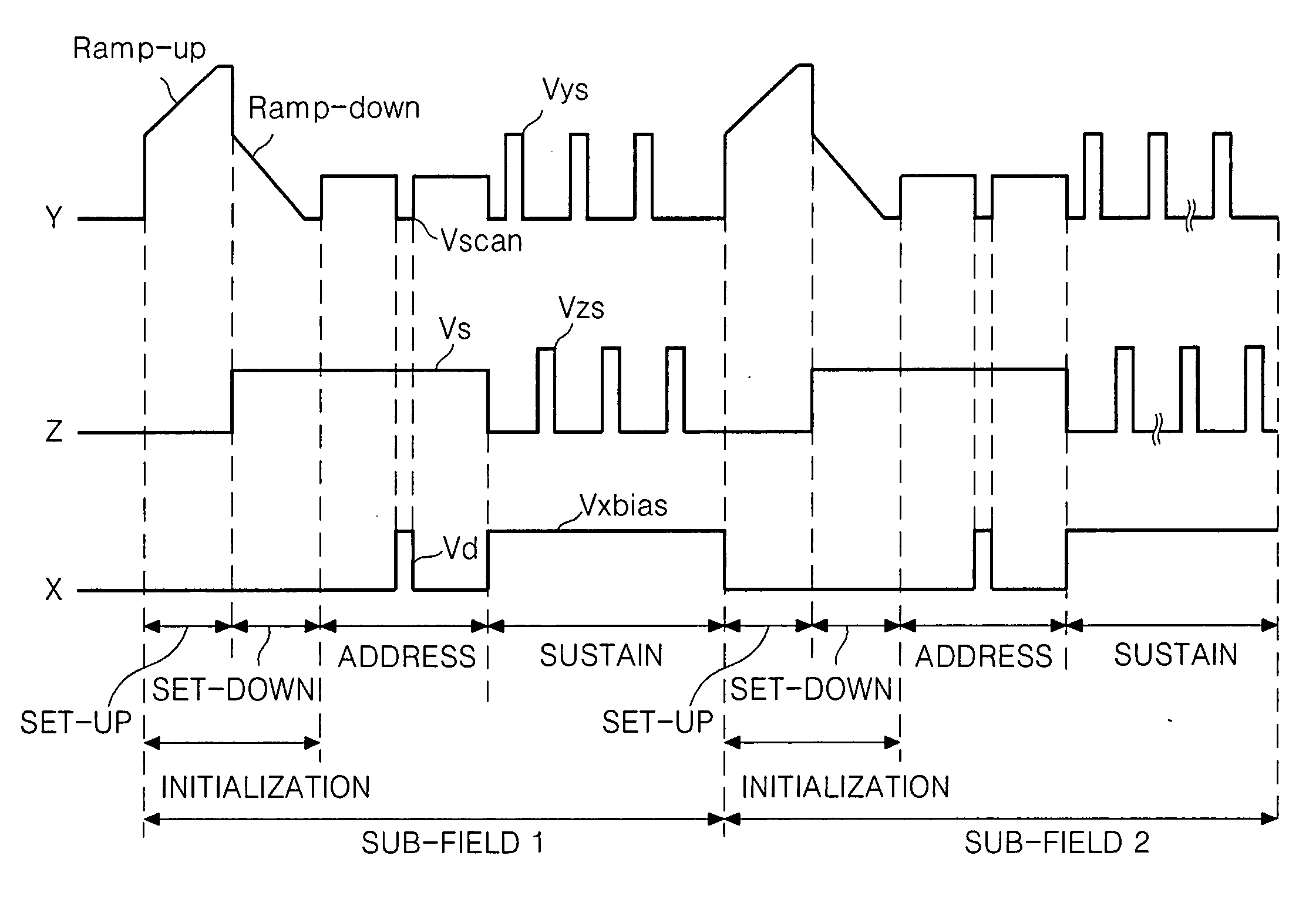
[0057]FIG. 10 is a waveform showing a method of driving a plasma display panel PDP according to an embodiment of the present invention.

[0058] Referring to FIG. 10, the method of driving the PDP is divided into an initialization period for initializing the full field, an address period for selecting a cell, and a sustaining period for sustaining a discharge of the selected cell for its driving.

[0059] In the initialization period, a rising ramp waveform Ramp-up is simultaneously applied to all the scan electrodes Y in the set-up interval. This rising ramp waveform Ramp-up causes a weak discharge within cells at the full field to generate wall charges within the cells. In the set-down interval...


PUM


Abstract

This invention relates to a method of driving a plasma display panel that is adaptive for generating a stable sustain discharge in a low opposition discharge voltage to improve a driving efficiency. A method of driving a plasma display panel, time-dividedly driven by dividing a plurality scan electrodes, sustain electrodes, and address electrodes into an initialization period, an address period, and a sustaining period, according to the present invention includes: applying a positive direct current voltage to the address electrode in the sustaining period; and applying a positive first sustaining pulse to the scan electrode and a positive second sustaining pulse to the sustain electrode, in the sustaining period.

Description

[0001] This application claims the benefit of Korean Patent Application No. P2004-82239 filed in Korea on Oct. 14, 2004, which is hereby incorporated by reference. BACKGROUND OF THE INVENTION [0002] 1. Field of the Invention [0003] This invention relates to a method of driving a plasma display panel, and more particularly, to a method of driving a plasma display panel that is adaptive for generating a stable sustain discharge in a low opposition discharge voltage to improve a driving efficiency. [0004] 2. Description of the Related Art [0005] Generally, a plasma display panel (PDP) radiates a phosphorous material using an ultraviolet ray with a wavelength of 147 nm generated upon discharge of an inactive mixture gas such as He+Xe, Ne+Xe or He+Ne+Xe, to thereby display a picture including characters and graphics. Such a PDP is easy to be made into a thin-film and large-dimension type. Moreover, the PDP provides a very improved picture quality owing to a recent technical development. ...

Claims


Application Information

Patent Timeline
IPC IPC(8): G09G3/28G09G3/20G09G3/288G09G3/291G09G3/292G09G3/293G09G3/294G09G3/298
CPCG09G3/294G09G3/2942G09G2320/0228G09G3/296
Inventor KIM, MIN SOOKIM, WON JAECHO, KI DUCKLEE, SUNG IM
Owner LG ELECTRONICS INC
Why Eureka
Try Eureka