Opto-electrochemical sensing system for monitoring and controlling industrial fluids

a sensing system and optoelectrochemical technology, applied in the direction of material electrochemical variables, instruments, fluorescence/phosphorescence, etc., can solve the problems of insufficient monitoring of most industrial process fluids, inaccurate measurements, and lack of sensitivity of configuration, so as to achieve rapid and accurate measurement of opto-electrochemical properties

Active Publication Date: 2017-04-04
CHEM AQUA INC +1
View PDF41 Cites 3 Cited by
  • Summary
  • Abstract
  • Description
  • Claims
  • Application Information

AI Technical Summary

Benefits of technology

[0010]This invention provides a system and method to determine properties of a fluid or fluid mixture based on both optical and electrochemical measurements of a sample and to control the operating parameters of a fluid system based on those properties. A sensing system according to a preferred embodiment of the invention can be used to rapidly and accurately measure the opto-electrochemical properties of a fluid or fluid mixture and comprises a sample cell and integrated optical and electrical components in a portable, handheld device. The system can be configured to determine various fluid properties of a sample using fluorescence, absorbance, transmission, or any other light-based measurement technique. The system can also be configured to substantially simultaneously determine various fluid properties of the same sample using integrated electrochemical components to measure conductivity, cyclic voltammetry, open circuit potential, or oxidation-reduction potentials.
[0011]A sensing system according to a preferred embodiment of the invention comprises a sample cell, at least one light source configured to direct light through a sample in the sample cell, at least one an optical sensor, at least two electrodes partially disposed in contact with the sample, an electronic module that controls the testing / measuring and for processing data received from the optical sensor and electrodes, and a small, handheld housing enclosing the sample cell, light source, optical sensor, electrodes, and electronic module. The housing preferably allows the sample to be added to the sample cell through a port in the housing, allowing the outside of the housing to be wetted but protecting the electronic module or other sensitive internal components of the sensing system. After adding a sample from a fluid system to the sample cell through the port in the housing, the sample is tested within the sample cell using a selected test configuration of the particular version of device (based on the various properties to be measured), and the sample could be eliminated from the sensing system by inverting the device so that the sample is drained from sample cell by gravity. Repeat measurements could be made by simply adding a new sample to the sample cell of the device, and different fluids could be measured using the same sample cell. Most preferably, the sample cell is rinsed a few times with water (deionized or distilled, preferably) or with a portion of the next sample to be measured. The sensing system is designed to be portable and powered by batteries, solar panels, DC or other portable power sources. The sensing system does not require the use of pumps or chemical injection to perform the various opto-electrochemical tests. Additionally, the preferred use of a sample cell to temporarily contain a sample to be tested eliminates inaccuracy problems associated with dip or immersion-type sensors or flow cell sensors.
[0013]According to another preferred embodiment, information regarding the measured or calculated properties of the fluid sample is used to control operating parameters of a fluid system from which the sample was obtained. The operating parameters (such as rate or amount of treatment product(s) added, “fresh” water or fluid added, blowdown, feed or other fluid system adjustments) may be altered (such as by opening or closing valves in the fluid system, operating pumps, or through manual addition of treatment products or chemicals) if the information indicates a change is needed, such as when the calculated value of a property falls outside a specified range for that property or is above or below a pre-set threshold value for that property. Additionally, calculated values may be compared and the difference may indicate a need to alter or automatically trigger an alteration in operating parameters for the fluid system, which may improve accuracy in controlling the fluid system.

Problems solved by technology

This configuration is known to lack sensitivity as demonstrated in FIG. 5 of the '809 patent, where the range of change is small, and would be insufficient for monitoring most industrial process fluids.
These instruments are immersed into the water being tested, which may result in inaccurate measurements.
The complexity of the multi-component sensor system in the '062 patent also requires the conductance electrodes to be floated while taking measurements with the other electrochemical electrodes, creating a risk of inaccurate bridge balance when making a conductance measurement.
Measuring conductivity with flowing fluid, and where mixing in a square cell configuration, would be prone to errors.
The measurement approach disclosed in the '652 patent would be inappropriate for a bulk fluid or fluid mixtures.
None of the known references disclose a single unit having multiple light sources and multiple optical detectors to measure multiple properties on a single sample contained within a sample cell.
Additionally none of the known references disclose combining optical property detection with detection of multiple electrochemical properties, through the use of two or more electrodes, in a single device.
Nor do any of the known references disclose comparing the results of an optical measurement with an electrochemical measurement obtained by a single device to enhance the control of a fluid system.

Method used


Image

  • Opto-electrochemical sensing system for monitoring and controlling industrial fluids
  • Opto-electrochemical sensing system for monitoring and controlling industrial fluids
  • Opto-electrochemical sensing system for monitoring and controlling industrial fluids

Examples


Embodiment Construction

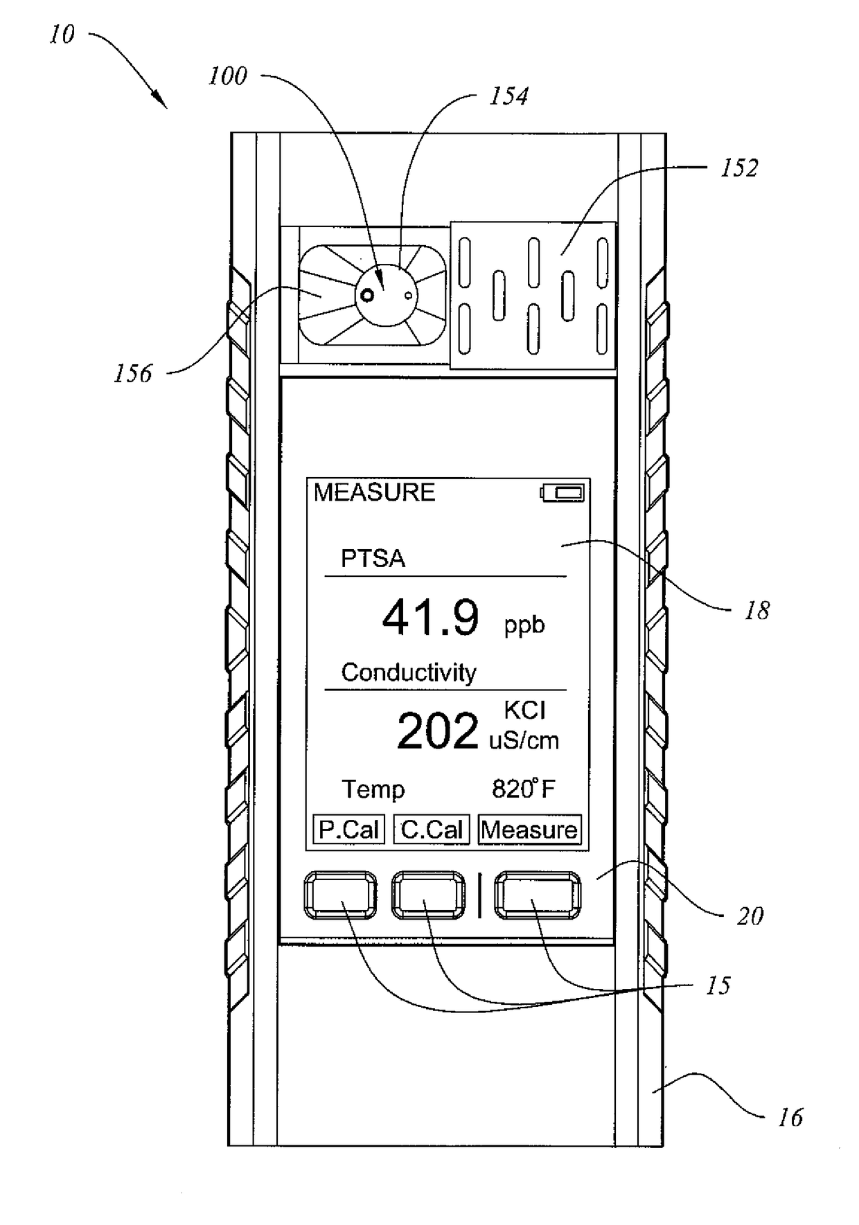
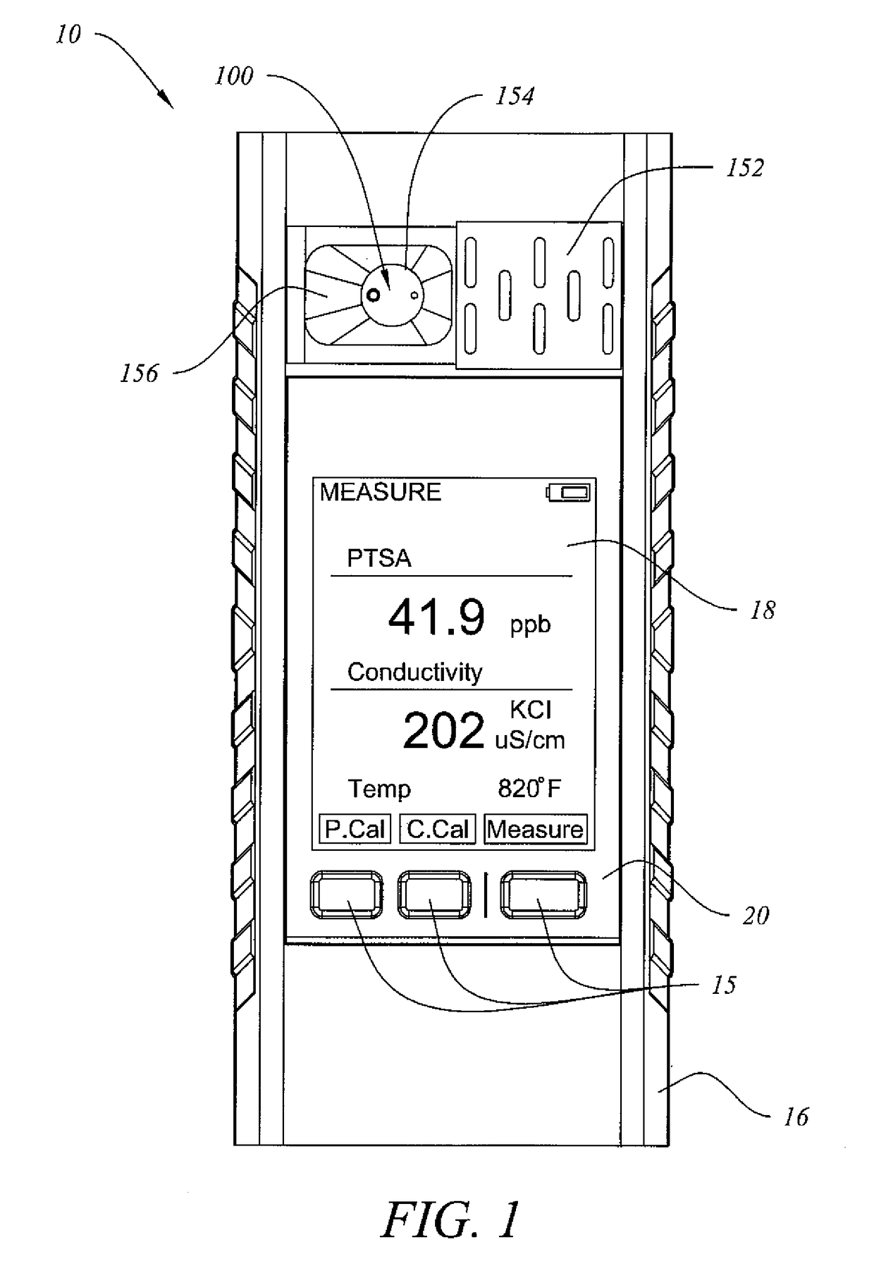
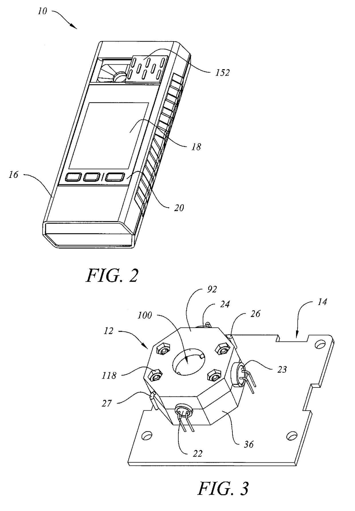
[0027]FIGS. 1-9 depict an electrochemical-optical sensing system 10 according to a preferred embodiment of the invention. Electrochemical-optical sensing system 10 preferably comprises electro-optical housing 12, printed circuit board 14, external housing 16, display 18, control panel 20, a sample receptacle for containing a sample of water or other fluid to be analyzed and formed at least in part by sample cell 80 and portions of electro-optical housing 12, at least one light source 22 (and most preferably two light sources 22, 23), at least one optical detector or sensor 24 (and most preferably two optical detectors or sensors 24, 25), and at least two electrodes 26, 27 that allow optical measurements and electrochemical measurements of the sample. The specific model shown in FIGS. 1-9 is designed to measure conductivity and fluorescence of aqueous process fluid samples obtained from a fluid system, such as a cooling tower or a boiler system. Conductivity is a common way to measur...


PUM

PropertyMeasurementUnit
internal volumeaaaaaaaaaa
wavelength rangeaaaaaaaaaa

Abstract

A system and method for controlling operating parameters of an industrial fluid system based on measurement of optical and electrochemical properties. The system comprises a handheld or portable meter that can substantially simultaneously measure one or more optical properties and one or more electrochemical properties of a sample of fluid from the fluid system. Information based upon the measurements or calculations made by the system may be used to manually or automatically alter various operating parameters to control the fluid system and aid in maintaining stable operation of the fluid system within preferred specifications.

Description

BACKGROUND OF THE INVENTION[0001]1. Field of the Invention[0002]This invention relates to measuring opto-electrochemical properties of a fluid or fluid mixture, or other properties of the fluid or fluid mixture based on the opto-electrochemical properties, using a simple integrated sensing cell. The system would be used to measure or calculate the properties of industrial fluids or fluid mixtures, and provide the necessary information to properly control the operation and treatment of an industrial fluid system.[0003]2. Description of Related Art[0004]Accurate measurement of various properties in industrial fluid systems, such as cooling towers and boiler systems, is required to assure proper performance, safety, and reliability of the fluid system, and to reduce unit lifetime costs of components in the fluid system. There are numerous sensing methods used to measure process fluids, but two of the more common are optical and electrochemical. Typically, measurement of an optical prop...

Claims


Application Information

Patent Timeline
Patent Type & Authority Patents(United States)
IPC IPC(8): G01N27/27G05D7/06G01N21/64G01N21/51G01N21/59
CPCG01N27/27G01N21/645G01N21/51G01N21/59G01N2021/6491G01N2201/0221G01N2201/062G01N27/08G01N27/4168
Inventor XIAO, CAIBINGU, JACKEYBOYETTE, SCOTT M.MURRAY, JEROLD
Owner CHEM AQUA INC
Why Eureka
Try Eureka