Method for correcting hole sites on basis of framework scanning measurement

A hole position and skeleton technology, which is applied in the field of hole position correction based on skeleton scanning measurement, can solve problems such as the inability to measure the distance between the hole position of the wall plate and the edge of the skeleton, the failure to meet the requirements of the hole making process, the deformation of the wing skeleton and the wall plate, etc. , to achieve the effect of solving the difficult measurement of edge distance, improving the efficiency of hole making and high degree of automation

Active Publication Date: 2014-07-02
ZHEJIANG UNIV
View PDF6 Cites 12 Cited by
  • Summary
  • Abstract
  • Description
  • Claims
  • Application Information

AI Technical Summary

Problems solved by technology

[0004] However, during the assembly process of the wing, due to the characteristics of the parts and the assembly method, its own stiffness and strength are often relatively insufficient, which causes deformation of the wing skeleton and wall panels.
Due to the accumulation of deformation error, positioning error and assembly error, the actual hole position on the skeleton and wall board deviates from the theoretical design position. If the hole is still made according to the theoretical position, the hole making position will be inaccurate, which does not meet the hole making process. requirements, serious damage to the aircraft structure leads to the generation of scrap parts
[0005] The traditional method is to rely on workers to draw lines to ensure the hole spacing and hole edge distance, or to use robots to trace points first and then manually measure whether the hole positions meet the requirements. This method first leads to low hole making accuracy and low hole making efficiency; It is impossible to measure the closed structure. After the wall plate and the frame are combined, the distance between the hole position of the wall plate and the edge of the frame cannot be measured

Method used


Image

  • Method for correcting hole sites on basis of framework scanning measurement
  • Method for correcting hole sites on basis of framework scanning measurement
  • Method for correcting hole sites on basis of framework scanning measurement

Examples


Embodiment Construction

[0044] The present invention will be described in detail below in conjunction with specific embodiments.

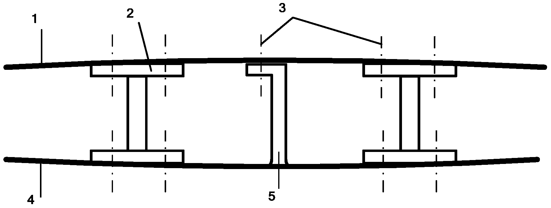
[0045] The hole position correction method based on skeleton scanning measurement in this embodiment relies on the following aircraft automatic assembly system for implementation. Before correcting the hole position, the following preparatory work should be carried out:

[0046] Lift the skeleton of the wing of the aircraft to the positioning tool;

[0047] Connect the measurement control computer, measurement automation interface box, and laser tracker, adjust the direction of the laser tracker to capture and lock the laser scanner, establish a complete measurement data transmission channel, and prepare for scanning measurement;

[0048] Set the scanning route to the CNC machine tool through the control system. The scanning path is based on the principle of reducing redundant measurement data and avoiding space obstacles, and can scan the skeleton completely.

[0049] A...


PUM


Abstract

The invention provides a method for correcting hole sites on the basis of framework scanning measurement. The method for correcting the hole sites includes computing rotation matrixes and translation vectors according to actual point cloud data and theoretical models of frameworks; correcting theoretical hole sites on the frameworks by the aid of the rotation matrixes and the translation vectors to obtain corrected hole sites; determining boundary lines of the various corrected hole sites; utilizing distances from the centers of the corrected hole sites to the boundary lines as corrected hole drilling edge distances. The method has the advantages that the problem of difficulty in measuring edge distances of closed structures can be solved; integral procedures are implemented on the basis of digitalization, accordingly, manual measurement can be omitted, and technological processes can be simplified; the problem of hole site inaccuracy due to the fact that hole sites are manually corrected after involution is performed by the aid of an existing method can be solved, and the automatic hole drilling precision can be guaranteed; the hole sites are firstly corrected before the hole drilling edge distances are determined, and the corrected hole sites can be acquired, so that hole site inaccuracy due to deformation, positioning and coordination can be eliminated, and the automatic hole drilling precision can be guaranteed.

Description

technical field [0001] The invention relates to the field of aircraft manufacturing, in particular to a hole position correction method based on skeleton scanning measurement. Background technique [0002] In the field of aircraft manufacturing, the connection of aircraft components is an important part of assembly, which largely determines the final quality, manufacturing cost and delivery cycle of the aircraft, and is the key and core technology in the entire aircraft manufacturing process. Large-scale aircraft are generally assembled by butt joints of multiple fuselage sections, and each fuselage section is assembled and spliced ​​by several wall panels. As one of the important components of modern large aircraft, the wall panel is not only an important part of the aerodynamic shape of the aircraft, but also the main load-bearing components of the fuselage and wings. [0003] Such as figure 1 As shown, the aircraft wing only has an upper wall plate 1, a skeleton 2 and a...

Claims


Application Information

Patent Timeline
Patent Type & Authority Applications(China)
IPC IPC(8): B64F5/00B64F5/10
Inventor 王青李江雄柯映林
Owner ZHEJIANG UNIV
Why Eureka
Try Eureka