Cylindrical-rod device for controlling a variable-pitch vane of a turbomachine

a turbomachine and variable-pitch technology, applied in the field of aircraft, can solve the problems of lack of accuracy in positioning the rod, the inability to control the pivot of the control rod relative to the vane, and the damage to the good operation of the assembly, so as to eliminate the inaccuracy of positioning

Active Publication Date: 2008-02-07
SN DETUDE & DE CONSTR DE MOTEURS DAVIATION S N E C M A
View PDF4 Cites 13 Cited by
  • Summary
  • Abstract
  • Description
  • Claims
  • Application Information

AI Technical Summary

Benefits of technology

[0006]A main object of the present invention is thus to mitigate such drawbacks by proposing a variable-pitch vane control device that enables the rod to be held without slack on the pivot of the vane to be controlled so as to eliminate inaccuracy in positioning, without requiring additional parts to be added.

Problems solved by technology

In that prior art, the lack of accuracy in control rod turning relative to the vane pivot lies in the range 0.5° to 0.7° (because of manufacturing tolerances).
This lack of accuracy in positioning the rod is particularly harmful to good operation of the assembly as a whole).

Method used


Image

  • Cylindrical-rod device for controlling a variable-pitch vane of a turbomachine
  • Cylindrical-rod device for controlling a variable-pitch vane of a turbomachine
  • Cylindrical-rod device for controlling a variable-pitch vane of a turbomachine

Examples


second embodiment

[0047]FIGS. 5 to 9 show the invention in which the clamping means exert clamping in a direction that is substantially parallel to the longitudinal axis X-X of the rod 14.

first embodiment

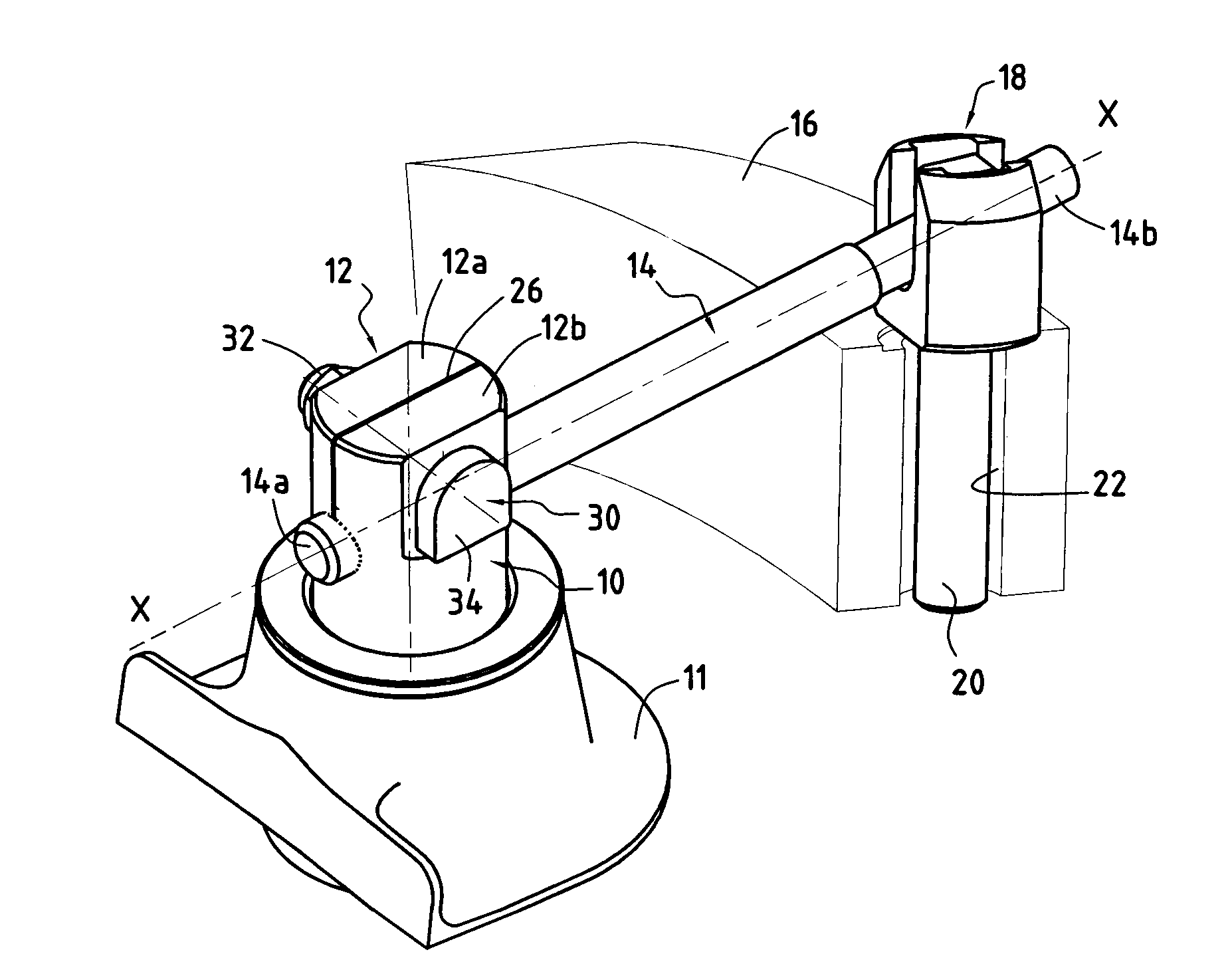
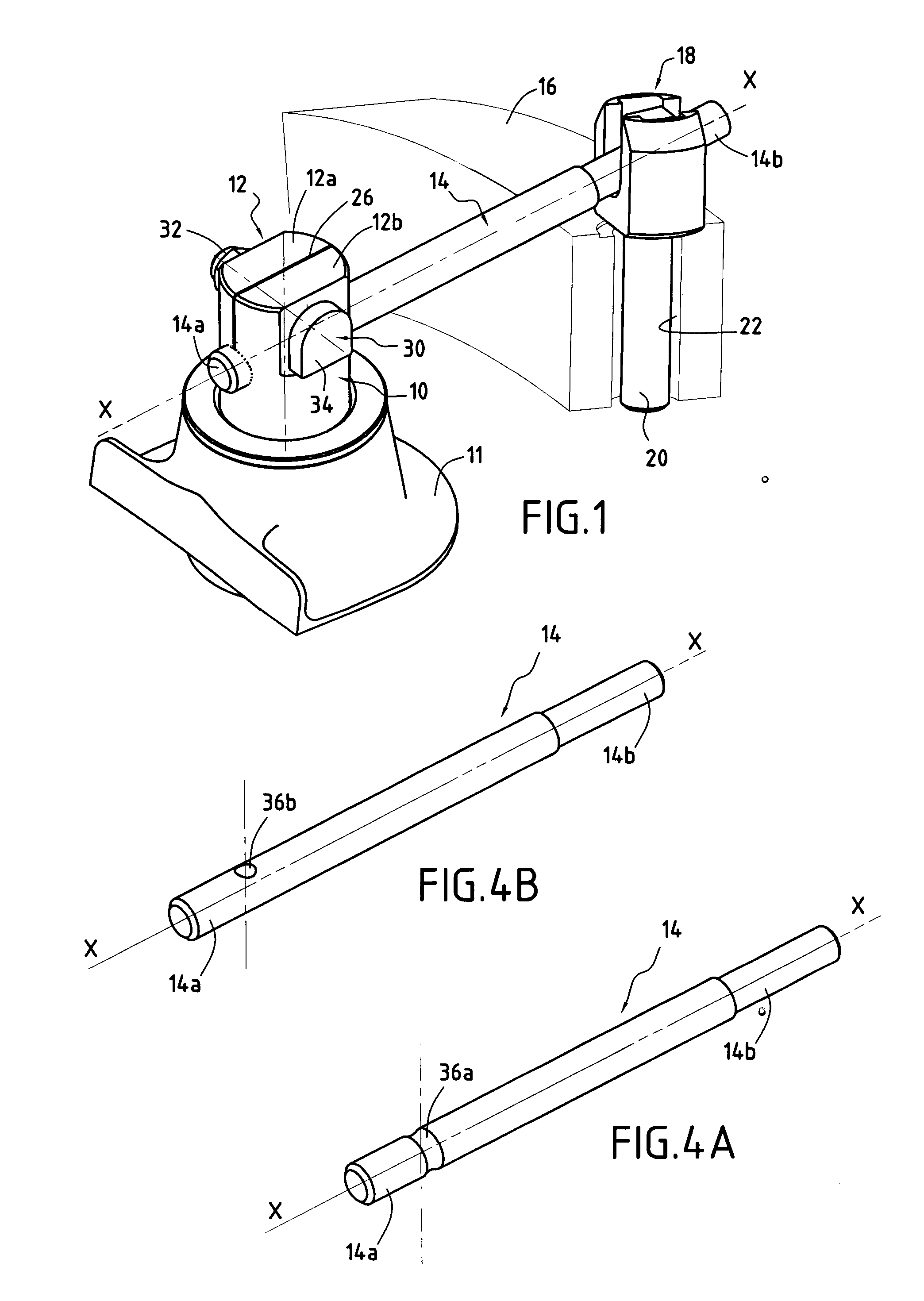
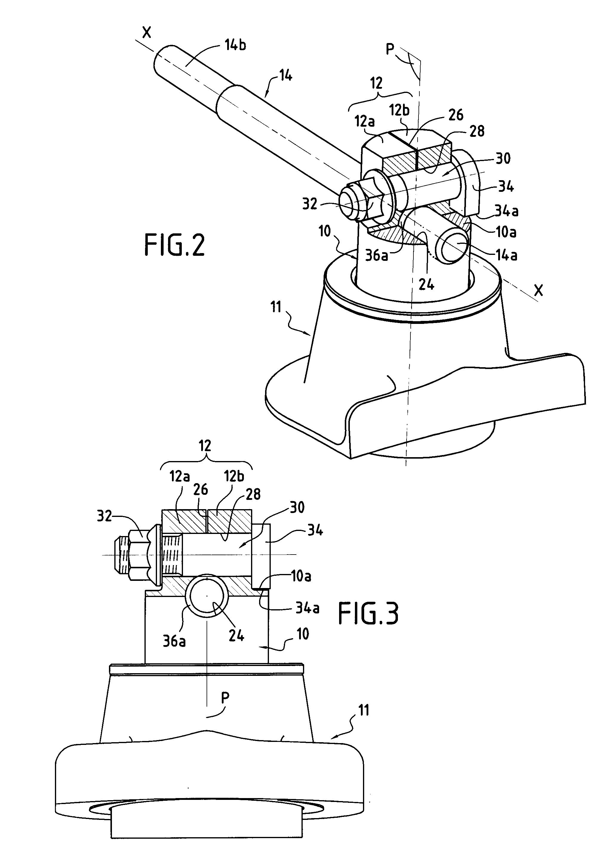
[0048]In these figures, the same references are used to designate elements of the control device that are the same as those described above with reference to the

[0049]In this second embodiment of the invention, the first end 14a of the cylindrical rod 14 is threaded, and the bore 24 of the pivot 10 of the vane comprises three portions: two end portions 24a, 24b that are substantially frustoconical in shape and that open to the outside of the pivot, and a central portion 24c that is substantially cylindrical, interconnecting the two end portions 24a, 24b (FIGS. 6 and 9).

[0050]In a variant of this second embodiment, shown in FIGS. 5 and 6, the first end 14a of the rod 14 also includes a collar 38 having a substantially conical bearing surface that co-operates with one of the end portions 24b of the bore 24 in the pivot 10 of the vane.

[0051]The control device also includes a clamping part 40 having a portion of substantially frustoconical shape mounted around the first end 14a of the r...


PUM


Abstract

The invention relates to a variable-pitch control device for a turbomachine compressor, the device comprising a rod, means for fastening a first end of the rod to a pivot of a vane to be controlled, and connection means between a second end of the rod and a control ring. The rod is substantially cylindrical, its first end being engaged in a bore in the pivot of the vane. The device further includes clamping means for clamping the first end of the rod in the bore in the pivot in order to fasten it to said pivot.

Description

BACKGROUND OF THE INVENTION[0001]The present invention relates to the general field of controlling variable-pitch vanes. A particular application lies in the field of aviation, and in particular to controlling the angular positions of vanes directing air flow into turbomachine compressors.[0002]Known devices for controlling variable-pitch vanes in a turbomachine usually comprise a control member in the form of a ring surrounding a casing of the turbomachine and a plurality of levers or rods, each rod having a first end connected to the control ring via a hinge and a second end mounted on the pivot of a respective vane. Synchronized modification of the angular position of the vanes is achieved by turning the ring around the axis of the turbomachine.[0003]In order to be able to follow the turning movement of the ring, the connection between each rod and the ring includes at least one degree of freedom in rotation about an axis extending substantially radially relative to the ring. Nev...

Claims


Application Information

Patent Timeline
Patent Type & Authority Applications(United States)
IPC IPC(8): F01D17/16
CPCF04D29/563F01D17/162
Inventor BOURU, MICHEL ANDREVERBRUGGE, ANDRE REMI CLAUDE
Owner SN DETUDE & DE CONSTR DE MOTEURS DAVIATION S N E C M A
Why Eureka
Try Eureka