Locating device

A positioning device and a technology of positioning pins, which are applied in the measurement of positioning in boring machines/drilling machines, parts of boring machines/drilling machines, drilling/drilling equipment, etc., can solve the problems affecting wheel interchangeability, assembly, and wheel processing accuracy and processing consistency, increased wheel waste, etc., to achieve the effect of simple structure, satisfactory precision, and low manufacturing cost

Inactive Publication Date: 2009-11-04
CITIC DICASTAL
View PDF0 Cites 7 Cited by
  • Summary
  • Abstract
  • Description
  • Claims
  • Application Information

AI Technical Summary

Problems solved by technology

[0003] During actual processing, due to the deformation of the wheel spokes and the existence of processing burrs, the position of the positioning rod and the wheel is not fixed and unique, but often changes, which will affect the processing accuracy and consistency of the wheel, seriously affecting the Affect the interchangeability and assembly of the wheels, resulting in an increase in wheel waste

Method used


Image

  • Locating device
  • Locating device
  • Locating device

Examples


Embodiment Construction

[0013] The details and working conditions of the specific device proposed according to the present invention will be described in detail below in conjunction with the accompanying drawings.

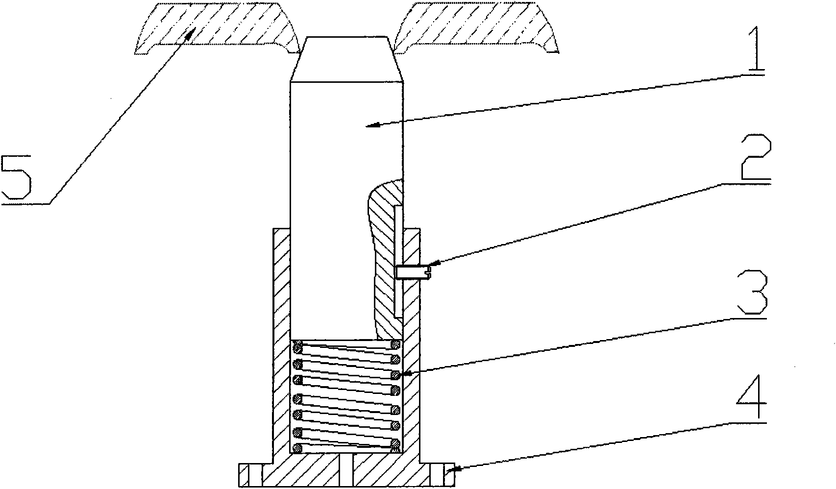
[0014] A positioning device of the present invention is composed of a conical positioning movable pin 1 , a limit screw 2 , a spring 3 and a base sleeve 4 . The conical positioning pin 1 and the spring 3 are installed in the base sleeve 4, the conical positioning pin 1 can slide up and down under the action of the spring 3, and the limit screw 2 is installed on the upper part of the base sleeve 4 to prevent the conical positioning pin 1 from detaching The angle of the base sleeve 4 and the tapered position of the tapered positioning pin 1 is 45° to 60°.

[0015] Before actual use, the tapered positioning pin 1 is at the highest position under the action of the spring 3 . In the course of work, the wheel 6 to be processed is first Figure 4 Placed on a machine tool fixture as shown. In ...


PUM


Abstract

The invention relates to a locating device which comprises a taper locating untie-sell 1, a stop screw 2, a spring 3, and a pedestal sleeve 4. The taper locating untie-sell 1 and the spring 3 are arranged inside the pedestal sleeve 4; the taper locating untie-sell 1 can slide up and down under the action of the spring 3; the stop screw 2 prevents the taper locating untie-sell 1 from breaking away the pedestal sleeve 4. The locating device can meet the positioning accuracy requirement of a wheel in use, does not care so much about the technology of an operator, has stable performance, simple structure, reliability, easy manufacture, and low manufacture cost.

Description

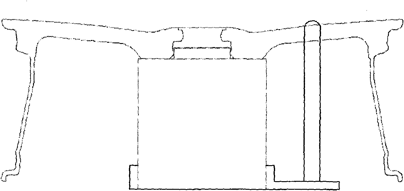
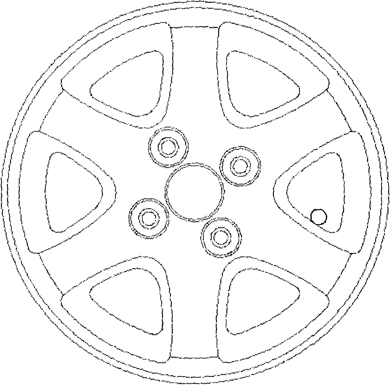
technical field [0001] The invention relates to a positioning device, in particular to a device for positioning in the circumferential direction by using a wheel window during wheel processing. Background technique [0002] In the drilling process of automobile wheels, it is necessary to locate the wheels in the axial, radial and circumferential directions, so as to limit the six degrees of freedom of the wheels. figure 1 is a common positioning method, figure 2 yes figure 1 top view. figure 1 Among them, the center hole and the flange face of the wheel are used for axial and radial positioning of the wheel, and the positioning rod passing through the window of the wheel is used for circumferential positioning. [0003] During actual processing, due to the deformation of the wheel spokes and the existence of processing burrs, the position of the positioning rod and the wheel is not fixed and unique, but often changes, which will affect the processing accuracy and consist...

Claims


Application Information

Patent Timeline
Patent Type & Authority Applications(China)
IPC IPC(8): B23B49/00
Inventor 郭建东房献忠李彬黄晓光栗志鹏康龙基贺峰
Owner CITIC DICASTAL
Why Eureka
Try Eureka