Test instrument probe with a pointed tip that is also capable of gripping

a test instrument and probe technology, applied in the field of electric test instrument probes, can solve the problems of affecting the concentration and integrity of the test procedure, affecting the accuracy of the test results, and often losing the clip

Active Publication Date: 2017-04-11
CHAIT PAUL NICHOLAS +1
View PDF14 Cites 3 Cited by
  • Summary
  • Abstract
  • Description
  • Claims
  • Application Information

AI Technical Summary

Benefits of technology

[0013]The present invention provides a test instrument probe that encompasses the dual alternate action of a point or a clamp-grip within the same probe. This probe invention has approximately the same dimensions as a conventional probe, and allows either the point or clamp action to be used without the necessity of removing the probe from the user's hand. This alternate action requires only using a thumb and finger pressure to change from a point to a clamp or the clamp to a point. The below described preferred embodiment of this point / grip invention allows a clamp jaw opening of nominal ¼ inch that is usually sufficient to grip onto the leads of an electronic component such as a resistor, capacitor or integrated circuit pin.
[0014]The probes of this invention are also designed so that when not in use, the two probes can be connected together by a snap-in action that minimizes the potential loss of a probe and importantly allows the points to become safely enclosed to minimize a sharp point hazard during carrying on the person, having on a bench-top, tool-case, etc.
[0016]It is another object of the present invention to provide a new and improved test instrument probe that can perform electrical testing with a minimum of distractions caused by changing probe tips.

Problems solved by technology

However, attaching the clip is time consuming and can interrupt the concentration and integrity of the testing procedure.
A clip is often lost or if a point probe is needed instead of a clamp the point probe may be unavailable.
This can lead to the use of the incorrect probe for the test application, with possible damage to the DUT or harm to the user.

Method used


Image

  • Test instrument probe with a pointed tip that is also capable of gripping
  • Test instrument probe with a pointed tip that is also capable of gripping
  • Test instrument probe with a pointed tip that is also capable of gripping

Examples


Embodiment Construction

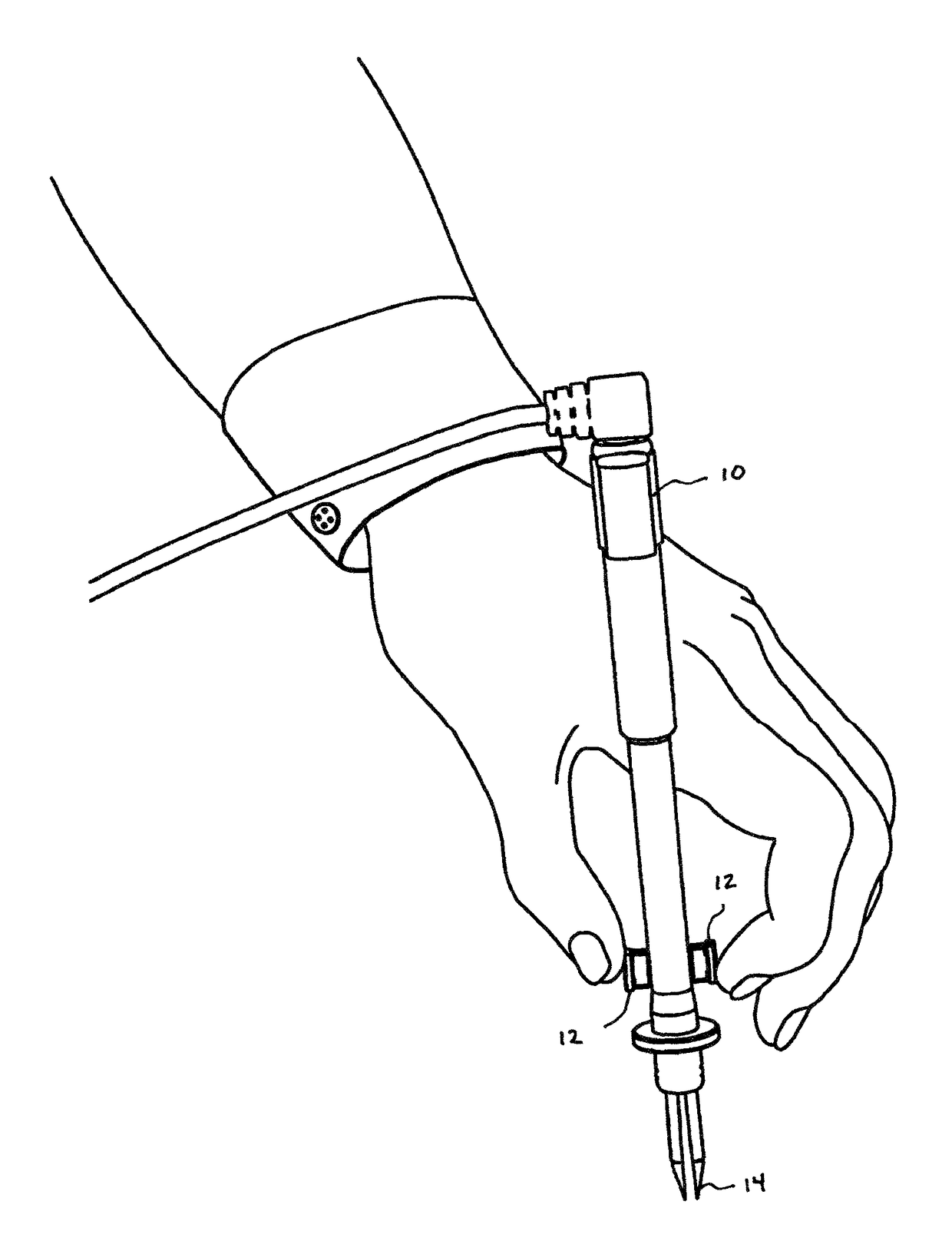
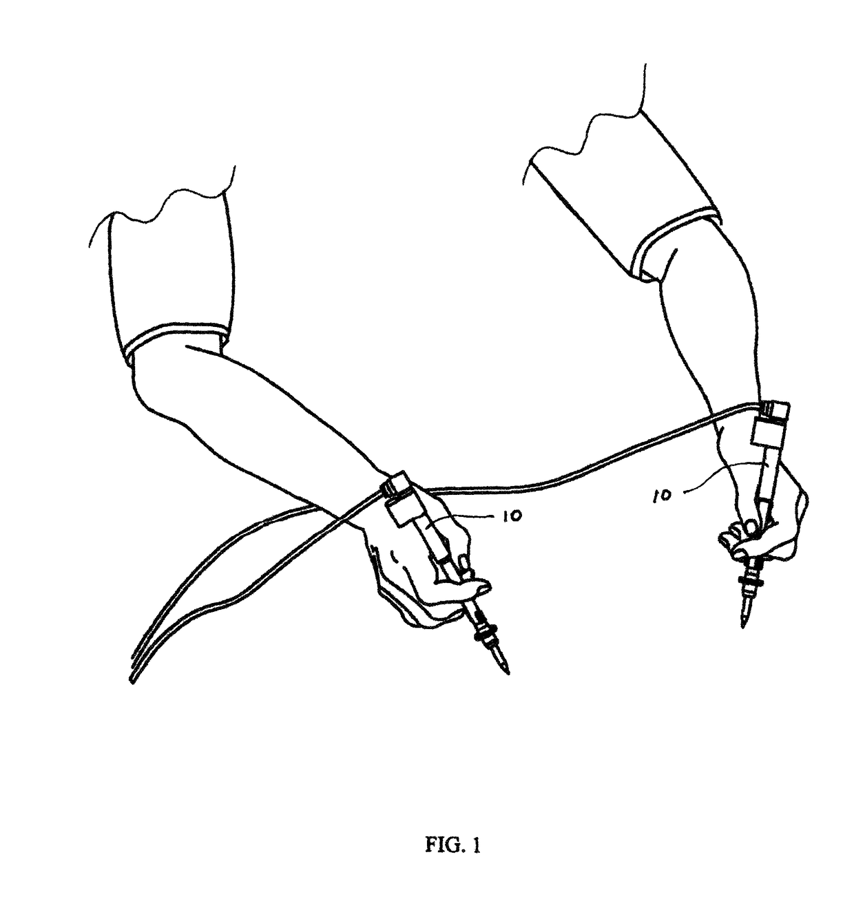
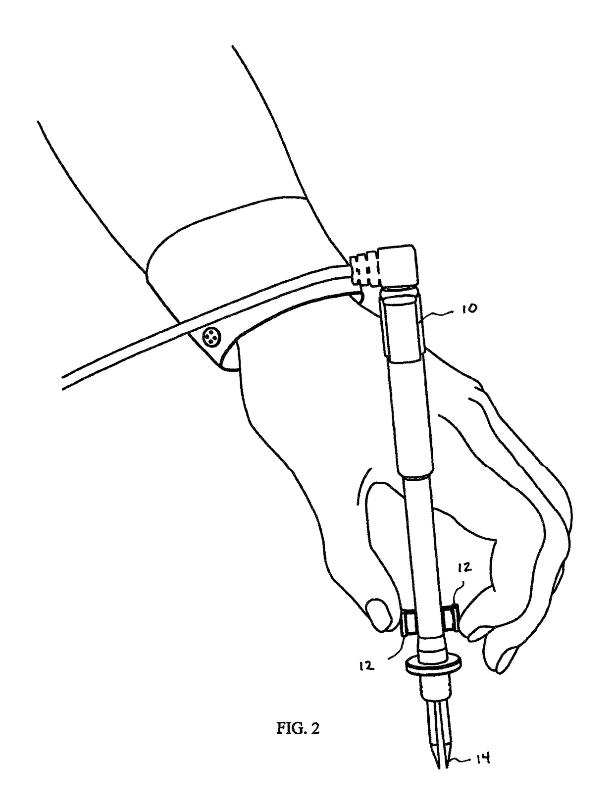
[0032]Referring to FIGS. 1 through 8C, wherein like reference numerals refer to like components in the various views, there is illustrated therein a new and improved multifunction test instrument probe, generally denominated 10 herein.

[0033]Both of the pair of probes of this point / grip invention are preferably identical except for a color that can identify, for example, positive as red and negative as black. The insulating enclosure or body of the probe is preferably a plastic tube and the point shaft emanating from the front of the tube is covered in plastic except for the tip that contacts the DUT. The insulated enclosure also has a finger guard near the front and two buttons whose operation is described below. Contained within the rear of the plastic enclosure is a socket into which the test lead connecting to the multi-meter is plugged. Also at the rear and part of the plastic enclosure is the plastic clamp into which the second probe may be snapped-in and retained together with...


PUM


Abstract

A test instrument probe that encompasses the dual alternate action of a point or a clamp-grip within the same probe. This probe has approximately the same dimensions as a conventional probe, and allows either the point or clamp action to be used without the necessity of removing the probe from the hand. This alternate action requires only using a thumb and finger pressure to change from a point to a clamp or the clamp to a point. One embodiment allows a clamp jaw opening of up to a nominal ¼ inch that is usually sufficient to grip onto the leads of an electronic component such as resistor, capacitor or integrated circuit pin. The probes are also designed so that when not in use, the two probes can be connected together by a snap-in action that minimizes the potential loss of a probe and importantly allows the points to become safely enclosed to minimize a sharp point hazard.

Description

CROSS REFERENCE TO RELATED APPLICATIONS[0001]The present application claims the benefit of the filing date of U.S. Provisional Patent Application Ser. No. 61 / 872,222, filed Aug. 30, 2013. The foregoing application is incorporated by reference in its entirety as if fully set forth herein.STATEMENT REGARDING FEDERALLY SPONSORED RESEARCH OR DEVELOPMENTREFERENCE TO A MICROFICHE APPENDIX[0002]Not applicable.TECHNICAL FIELD[0003]The present invention relates generally to electrical test instrument probes, and more particularly, to a test instrument probe with a pointed tip that is also capable of gripping.BACKGROUND INFORMATION AND DISCUSSION OF RELATED ART[0004]Probes for electrical test instruments such as those known as multi-meters or volt-ohmmeters are a necessary adjunct to most instruments during any testing procedure. The most common interface between the ‘Device Under Test’ (DUT) and the multi-meter is a pointed metallic tip of a probe. The overall length of a conventional probe ...

Claims


Application Information

Patent Timeline
Patent Type & Authority Patents(United States)
IPC IPC(8): G01R31/02G01R1/067B25B9/02G01R1/04
CPCG01R1/06788B25B9/02G01R1/0416G01R1/0425
Inventor CHAIT, PAUL NICHOLASCHAIT, STANLEY
Owner CHAIT PAUL NICHOLAS
Why Eureka
Try Eureka