Eureka AIR delivers breakthrough ideas for toughest innovation challenges, trusted by R&D personnel around the world.

Method for manufacturing energy harvester comprising piezoelectric polymer microstructure array

a microstructure array and energy harvester technology, applied in the field of micronano manufacturing technology, can solve the problems of low efficiency, low production cost, and inapplicability to miniaturization and intelligence of devices, and achieve the effects of improving the energy conversion efficiency of piezoelectric energy harvesters, reducing processing costs, and extending the depth

Active Publication Date: 2017-04-11
XI AN JIAOTONG UNIV
View PDF2 Cites 0 Cited by
  • Summary
  • Abstract
  • Description
  • Claims
  • Application Information

AI Technical Summary

Benefits of technology

[0006]In view of the above-described problems, it is one objective of the invention to provide a method for manufacturing an energy harvester comprising a piezoelectric polymer microstructure array. Under actions of both an electric field and a thermal field, a piezoelectric polymer is theologically transformed into a microstructure and is simultaneously polarized along a field direction thereby acquiring a strong piezoelectric property. Thus, a group of a piezoelectric polymer microstructure array connected to an upper electrode and a substrate is obtained and the final piezoelectric energy harvester is directly formed. The method of the invention reasonably integrates piezoelectric property and scale effect of the material. Not only is the piezoelectric microstructure array having a large depth to width ratio realized, but also processes of film preparation, stretching, electric polarization, and device package are simplified. Thus, the manufacturing procedure is shortened, the efficiency is improved, and requirements for batch production, low cost, and consistency are satisfied.
[0011]4) using a second FTO or ITO conductive glass as an upper electrode, and allowing the upper electrode and the substrate to form a pair of plate electrodes comprising an air gap therebetween; controlling the air gap between the upper electrode and the substrate to be between 2 and 4 times of a height of the column array by disposing a polyimide film of different thickness therebetween; placing the pair of the plate electrodes into the oven; applying an external DC power supply by connecting a positive electrode thereof to the upper electrode and connecting a negative electrode thereof to the substrate; raising the temperature of the oven to be higher than the glass transition temperature of the piezoelectric polymer; regulating a voltage whereby enabling an electric force applied on the column array of the piezoelectric polymer to counteract a surface tension and a viscous resistance rheology; and maintaining the voltage for between 20 and 50 min until the column array of the piezoelectric polymer reaching the upper electrode and forming a mushroom-shaped structure array; and
[0016]Advantages according to embodiments of the invention are summarized as follows: the method of the invention is applicable for a wide range of the piezoelectric polymer material, and the obtained piezoelectric energy harvester comprises the microstructure array having a large depth to width ratio, thereby greatly improving the energy conversion efficiency of the piezoelectric energy harvester. In addition, the method involves no complex processes, and the microstructure and electric polarization can be accomplished simultaneously. The manufacturing process of the device is one step formation, which largely decreases the processing cost and improves the processing efficiency. The device of the invention is adapted to broad application in fields of underwater acoustic detection, piezoelectric sensing, and ultrasonic transduction, and to realize wireless energy supply to low energy consumed products, such as wireless networks, embedded systems, and MEMS, thereby presenting good application prospects of the piezoelectric energy harvesting technology.

Problems solved by technology

However, such a method has a relatively high production cost, low efficiency, and is not applicable to miniaturization and intelligence of the device.
In addition, the high temperature calendaring and extrusion molding and the stretching process are difficult to implement in a silicon planar process in micro-electro-mechanical systems (MEMS).

Method used


Image

  • Method for manufacturing energy harvester comprising piezoelectric polymer microstructure array
  • Method for manufacturing energy harvester comprising piezoelectric polymer microstructure array
  • Method for manufacturing energy harvester comprising piezoelectric polymer microstructure array

Examples


Embodiment Construction

[0027]For further illustrating the invention, experiments detailing a method for manufacturing an energy harvester comprising a microstructure array of a piezoelectric polymer are described below. It should be noted that the following examples are intended to describe and not to limit the invention.

[0028]A method for manufacturing an energy harvester comprising a microstructure array of a piezoelectric polymer is conducted as follows:

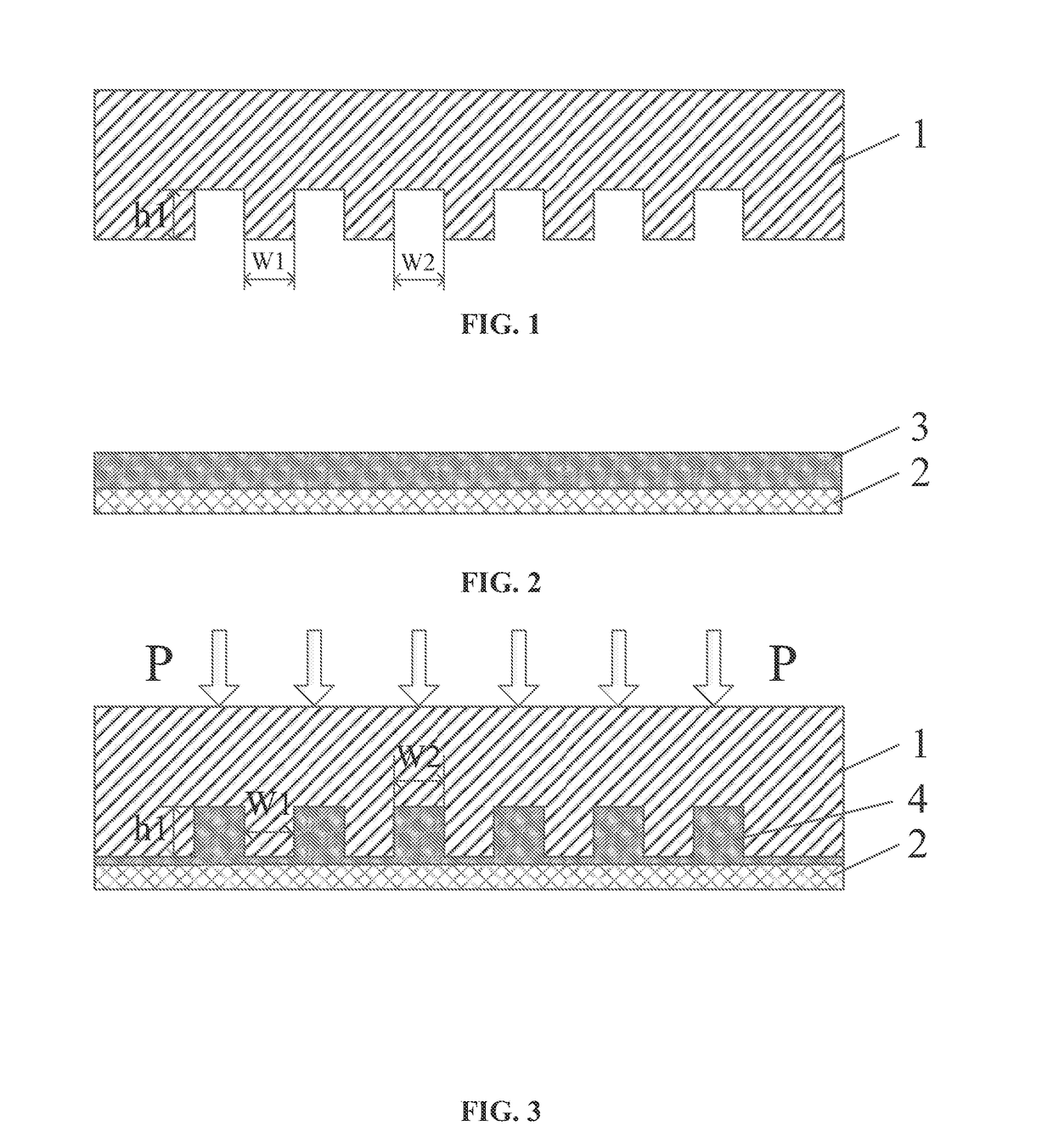
[0029]First, preparation and treatment of an imprint mold. As shown in FIG. 1, a micro-hole array is fabricated on a silicon chip by conventional photolithography and etching processes thereby obtaining an imprint mold 1. The imprint mold 1 is immersed in a fluorosilanes solution for 6 hrs and is then baked for 12 hrs for decreasing a surface energy, so that a micro-column array structure of the imprint mold is prevented from damage in demolding process.

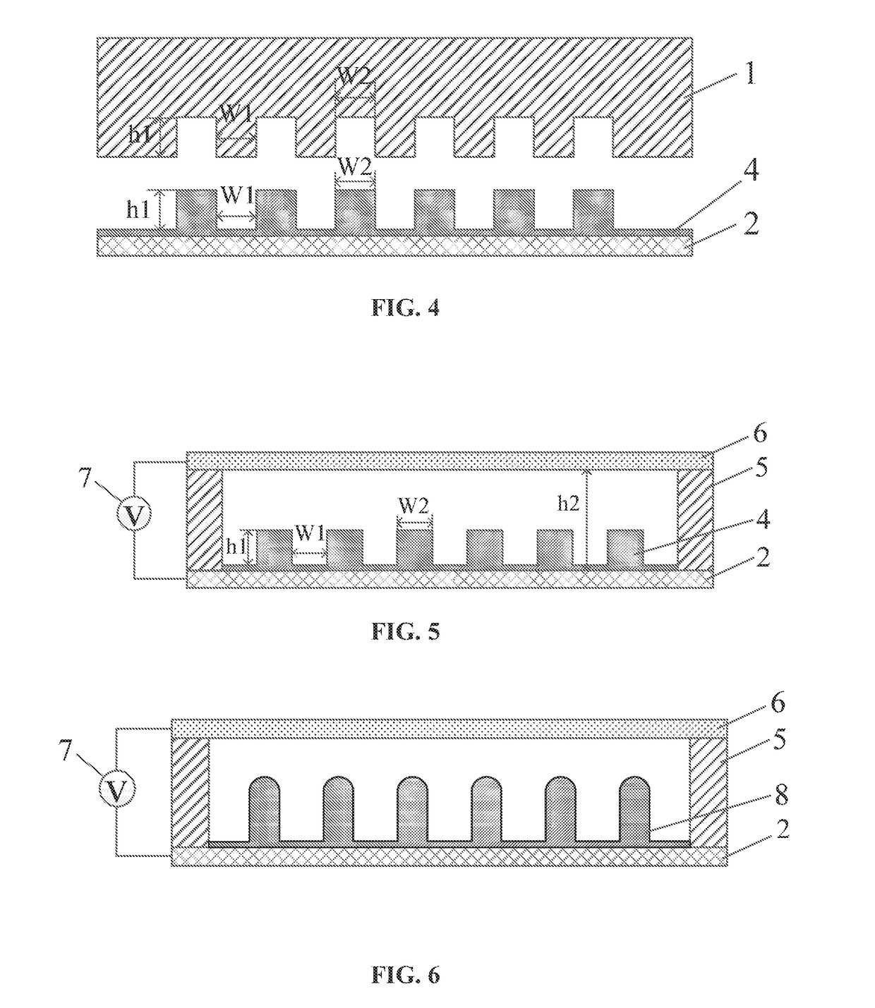
[0030]Second, selection and treatment of a substrate and an upper electrode. A first fluorine-doped t...


PUM

PropertyMeasurementUnit
pressureaaaaaaaaaa
temperatureaaaaaaaaaa

Abstract

A method for manufacturing an energy harvester including a piezoelectric polymer microstructure array. The method includes: preparing a micro-column array of a piezoelectric polymer on a substrate; supplying a plate electrode as an upper electrode, allowing the substrate and the upper electrode to form a pair of plate electrodes; applying a DC voltage between the pair of the plate electrodes; heating the substrate to a temperature higher than a glass transition temperature of the piezoelectric polymer and performing rheological formation of the micro-column array with the DC voltage still being applied until the column array of the piezoelectric polymer reaches the upper electrode to form a mushroom-shaped structure array; and cooling and solidifying the piezoelectric polymer to obtain the piezoelectric energy harvester.

Description

CROSS-REFERENCE TO RELATED APPLICATIONS[0001]This application is a continuation-in-part of International Patent Application No. PCT / CN2014 / 079030 with an international filing date of May 31, 2014, designating the United States, now pending, and further claims priority benefits to Chinese Patent Application No. 201410027619.1 filed Jan. 21, 2014. The contents of all of the aforementioned applications, including any intervening amendments thereto, are incorporated herein by reference. Inquiries from the public to applicants or assignees concerning this document or the related applications should be directed to: Matthias Scholl P.C., Attn.: Dr. Matthias Scholl Esq., 245 First Street, 18th Floor, Cambridge, Mass. 02142.BACKGROUND OF THE INVENTION[0002]Field of the Invention[0003]The invention relates to the field of the micro-nano manufacturing technology, and more particularly to a method for manufacturing an energy harvester comprising a piezoelectric polymer microstructure array.[000...

Claims


Application Information

Patent Timeline
Patent Type & Authority Patents(United States)
IPC IPC(8): H01L41/22H04R17/00H02N2/00H02N2/18
CPCH02N2/22H02N2/181H02N2/186Y10T29/42Y10T29/49124Y10T29/49153H02N2/18H10N30/857H10N30/084H10N30/098
Inventor SHAO, JINYOUDING, YUCHENGCHEN, XIAOLIANGZHOU, YAOPEITIAN, HONGMIAOLI, XIANGMING
Owner XI AN JIAOTONG UNIV
Why Eureka
Eureka Blog
Learn More