Heat transfer system two separate heat loops in exchange

Inactive Publication Date: 2017-04-18
AIRBUS DEFENCE & SPACE
View PDF18 Cites 1 Cited by
  • Summary
  • Abstract
  • Description
  • Claims
  • Application Information

AI Technical Summary

Problems solved by technology

This manner of operation limits by half the thermal performance of the heat transfer system.
However, these solut

Method used


Image

  • Heat transfer system two separate heat loops in exchange
  • Heat transfer system two separate heat loops in exchange
  • Heat transfer system two separate heat loops in exchange

Examples


Example

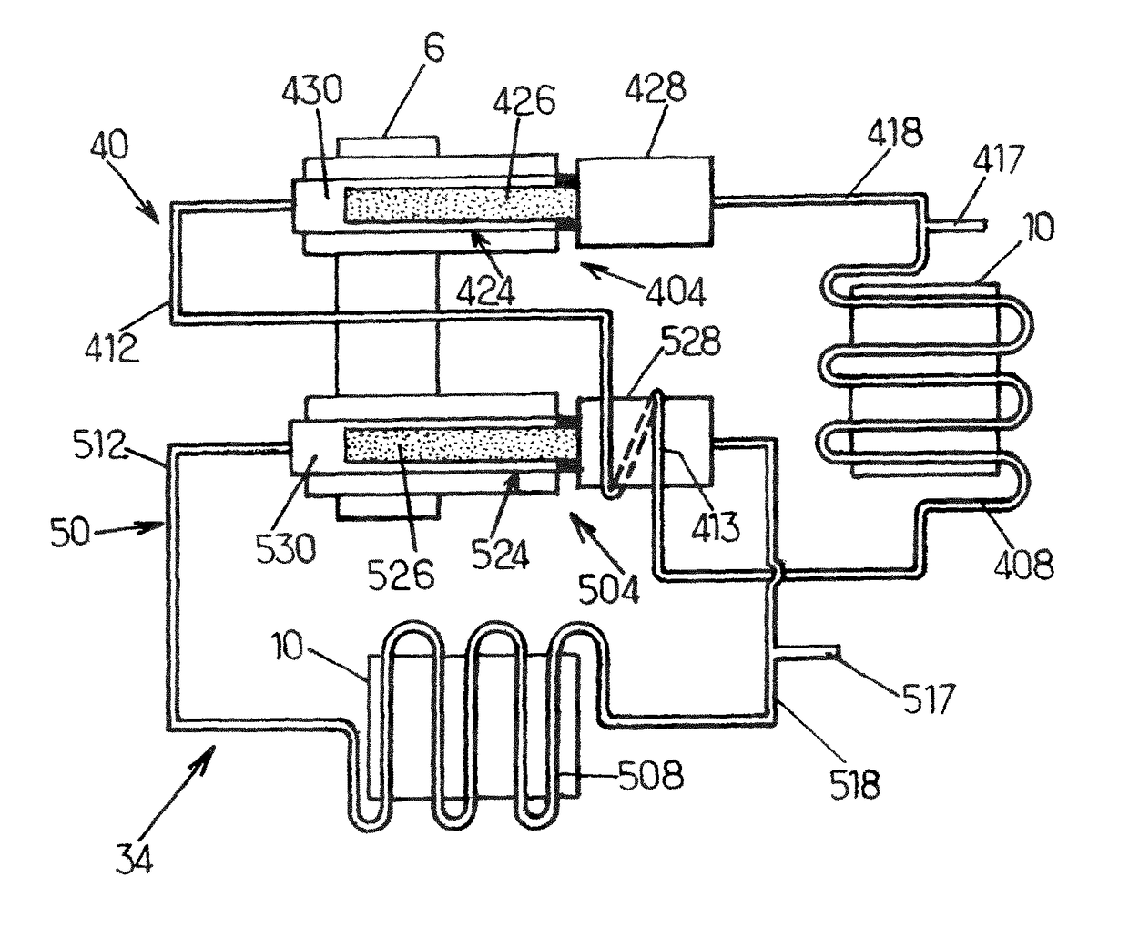
[0062]In this second embodiment operating according to a mode of operation called “hot redundancy”, the cooling fluid of the main fluid loop 60 is in heat exchange with the cooling fluid in the liquid state of the secondary fluid loop 70.

[0063]For example in FIG. 3, the cooling fluid contained in the liquid pipe 618 of the main fluid loop 60 is in heat exchange, by winding 619, with the cooling fluid contained in the reservoir 728 of the secondary fluid loop 70. Moreover, the cooling fluid contained in the fluid pipe 718 of the secondary fluid loop 70 is in heat exchange, by winding 719, with the cooling fluid contained in the reservoir 628 of the main fluid loop 60.

[0064]The heat exchange can be carried out by any other means, direct or indirect, such as those previously mentioned.

[0065]In a variant, the cooling fluid contained in at least one element of the cold part of the main fluid loop 60, preferably from the liquid pipe 618 including any derivation branch of this pipe, the re...


PUM


Abstract

The invention relates to a heat transfer system with one main capillary pumped diphasic fluid loop and a secondary capillary pumped diphasic fluid loop suitable for cooling at least one hot source. The main fluid loop and the secondary fluid loop have one evaporator, a vapor pipe capable of conveying the cooling fluid in the vapor state from the evaporator to a condenser, a condenser and a liquid pipe capable of conveying the cooling fluid in the liquid state from the condenser to the evaporator-so that the cooling fluid of the main fluid loop is in heat exchange with the cooling fluid of the secondary fluid loop.

Description

RELATED APPLICATIONS[0001]The present application is a National Phase entry of PCT Application No. PCT / EP2011 / 067406, filed Oct. 5, 2011, which claims priority from FR Application No. 1058185 filed Oct. 8, 2010, and FR Application No. 1004755, filed Dec. 7, 2010, all of which are hereby incorporated by reference herein in their entirety.FIELD OF INVENTION[0002]The invention relates to a heat transfer system comprising at least two capillary pumped diphasic fluid loops used for cooling at least one hot source.BACKGROUND OF THE INVENTION[0003]A capillary pumped diphasic fluid loop, often by misuse of language simply called a “fluid loop”, is a system that conveys thermal energy from a hot source to a cold source, by using capillarity as the driving pressure, and the (liquid-vapour) phase change is used as a means of conveying energy.[0004]Such a fluid loop generally comprises an evaporator intended to extract heat from a hot source and a condenser intended to return this heat to a col...

Claims


Application Information

Patent Timeline
IPC IPC(8): F28D15/00F28D15/04F28D15/02
CPCF28D15/043F28D15/0266F28D15/046
Inventor FIGUS, CHRISTOPHE
Owner AIRBUS DEFENCE & SPACE
Why Eureka
Try Eureka