
Two-phase heat-transfer systems

a heat-transfer system and two-phase technology, applied in the direction of indirect heat exchangers, machines/engines, lighting and heating apparatus, etc., can solve the problems of inability to achieve and achieving the effect of reducing the internal pressure of inactive airtight two-phase heat-transfer systems

Inactive Publication Date: 2005-03-15
MOLIVADAS STEPHEN
View PDF38 Cites 156 Cited by
  • Summary
  • Abstract
  • Description
  • Claims
  • Application Information

AI Technical Summary

Benefits of technology

The purpose of freeze protection is to prevent liquid refrigerant freezing in the principal configuration of an airtight configuration while the entire principal configuration, or while one or more parts of the principal configuration, are exposed to refrigerant subfreezing temperatures.
The purpose of liquid-refrigerant injection is to achieve at least one of several objectives. These objectives include (1) preventing refrigerant vapor being trapped in one or more parts of the evaporator refrigerant passages of a system of the invention, thereby eliminating potential hot spots; (2) increasing the refrigerant's heat-transfer coefficients in the system's evaporator refrigerant passages; and (3) increasing the refrigerant's critical flux in those passages.

Problems solved by technology

However, prior-art embodiments of such two-phase heat-transfer systems have often been unable to compete successfully with single-phase heat-transfer systems.
I also assert that the prior-art describes no generally useful techniques for eliminating air ingestion from internal-combustion-engine cooling systems without(a) constraining operating pressures to be essentially equal to the current atmospheric pressure or to differ from the current atmospheric pressure by a constant amount; or without(b) using expensive glandless valves, and hermetically-sealed pumps, and requiring unacceptably-thick refrigerant-passage walls; and, in the case of internal-combustion engines with separate cylinder blocks and cylinder heads, without also using impractical cylinder-head gaskets.
Nevertheless, the prior art discloses no techniques for maintaining the internal pressure of inactive airtight two-phase heat-transfer systems above their refrigerant saturated-vapor pressure without imposing at least one of the constraints recited above under (a) and (b).

Method used


Image

  • Two-phase heat-transfer systems
  • Two-phase heat-transfer systems
  • Two-phase heat-transfer systems

Examples


Embodiment Construction

A. General Remarks

The optimal number and kind of airtight configurations used in a system of the invention, the desired properties of those configurations, and the particular refrigerant—and where applicable inert-gas—control techniques employed to achieve those properties, depend on the particular heat-transfer application considered. It follows that the best mode for carrying out the invention, namely the preferred embodiment of a system of the invention, depends on the particular heat-transfer application considered.

In this part (part V) of this DESCRIPTION I first describe principal, ancillary, and IG, configurations suitable for various preferred embodiments of the invention, and then give examples of those embodiments in the context, for specificity, of a particular category of applications. Each of these embodiments is expected to be a preferred embodiment for some specific useful application. The statements made about the principal configurations of airtight configurations a...


PUM


Abstract

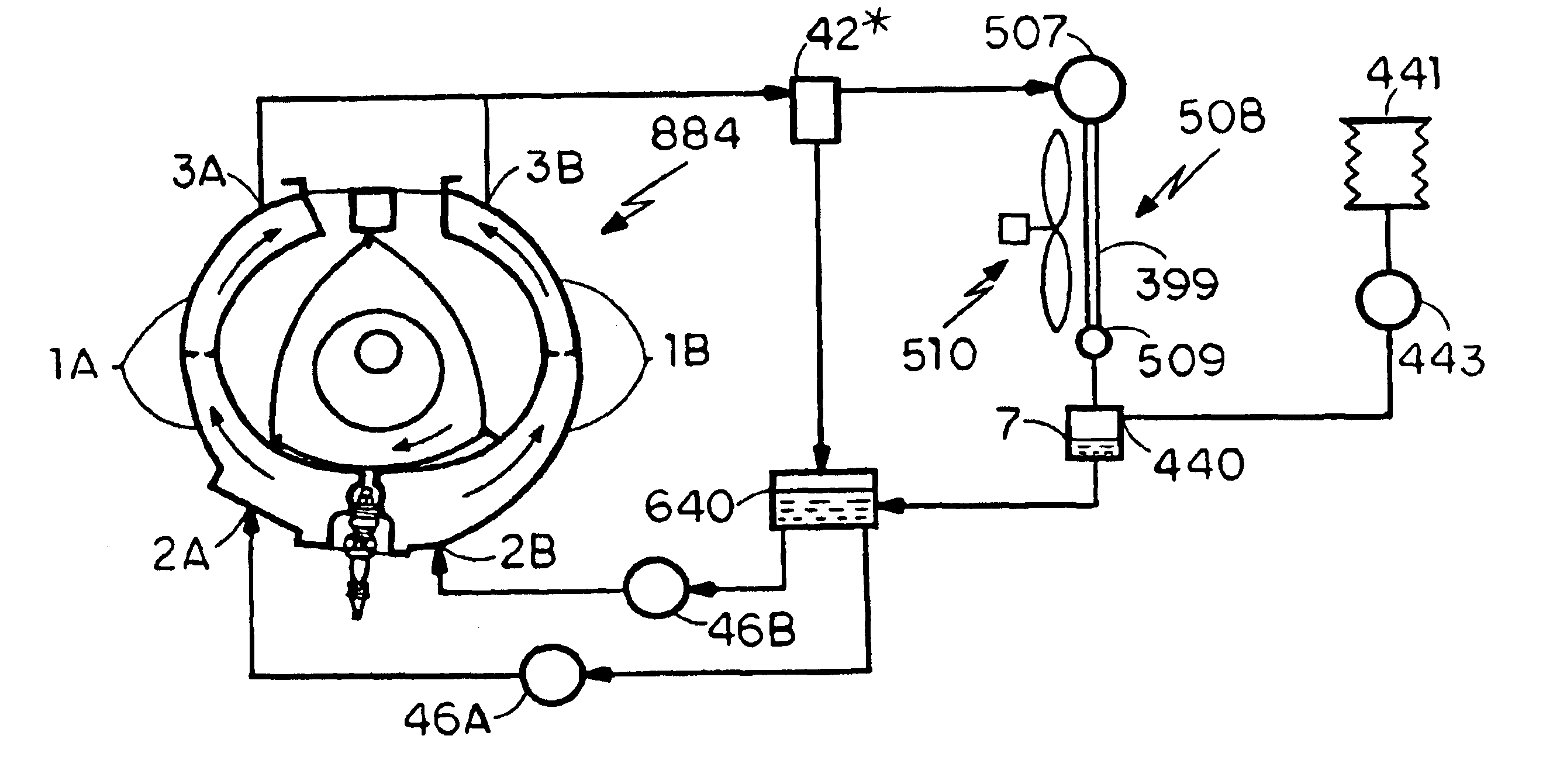
Various techniques are disclosed for improving airtight two-phase heat-transfer systems employing a fluid to transfer heat from a heat source to a heat sink while circulating around a fluid circuit, the maximum temperature of the heat sink not exceeding the maximum temperature of the heat source. The properties of those improved systems include (a) maintaining, while the systems are inactive, their internal pressure at a pressure above the saturated-vapor pressure of their heat-transfer fluid; and (b) cooling their internal evaporator surfaces with liquid jets. FIG. 43 illustrates the particular case where a heat-transfer system of the invention is used to cool a piston engine (500) by rejecting, with a condenser (508), heat to the ambient air; and where the system includes a heat-transfer fluid pump (10) and means (401-407) for achieving the former property.

Description

I. TECHNICAL FIELDThe general technical field of the present invention pertains to systems that include one or more fluid circuits for transferring heat from one or more heat sources to one or more heat sinks with a heat-transfer fluid circulating around the one or more fluid circuits; a heat sink—to which heat is released by the heat-transfer fluid—having, at an instant in time, a maximum temperature below the maximum temperature of the heat source from which the released heat is absorbed at that instant in time. Such heat-transfer systems—which by the foregoing description exclude heat pumps—can be grouped into two general categories:(a) single-phase heat-transfer systems having only fluid circuits whose heat-transfer fluid remains in the same phase (liquid or vapor phase) throughout a circulation cycle; and(b) two-phase heat-transfer systems, having at least one fluid circuit whose heat-transfer fluid changes—at least under some operating conditions—at least in part from its liqu...

Claims


Application Information

Patent Timeline
Patent Type & Authority Patents(United States)
IPC IPC(8): F01P11/02F01L3/00F01P11/00F01P3/22F02B29/04F01L3/12F02B29/00F25B23/00
CPCF01L3/12F01P3/22F01P11/02F02B29/0475F25B23/006F02B29/0443Y02T10/146F02F2007/0092Y02T10/12
Inventor MOLIVADAS, STEPHEN
Owner MOLIVADAS STEPHEN
Learn More