
System and method for determining a borehole azimuth using gravity in-field referencing

a technology of gravity infield and system, applied in the direction of gravity wave measurement, measurement devices, instruments, etc., can solve the problems of affecting magnetometers and gyroscopes that can be considered relatively complex instruments

Inactive Publication Date: 2017-04-18
MOSTAR DIRECTIONAL TECH
View PDF27 Cites 0 Cited by
  • Summary
  • Abstract
  • Description
  • Claims
  • Application Information

AI Technical Summary

Benefits of technology

The patent describes a method for determining the direction of a borehole using accelerometers. A first set of data is collected from an upper sensor module, and a second set of data is collected from a lower sensor module. Using these data sets, gravity components are determined and used to calculate the bend angle and tilt angle of the borehole. The change in displacement is then determined and outputted for analysis. This method can provide a more accurate means of determining borehole direction, which can be useful in the oil and gas industry for drilling wells.

Problems solved by technology

There are situations when magnetometers are affected by sources of magnetic interference such as nearby magnetic steel, electromagnetic radiation, ferric minerals in formations or ore bodies, and drilling string interference caused by motors and stabilizers.
A primary cause for concern with such magnetic interference is the deflection of the azimuth readings that are obtained using magnetometers.
Gyroscopes can be considered to be relatively complex instruments and often need to be frequently re-referenced and protected from high temperatures and vibration.

Method used


Image

  • System and method for determining a borehole azimuth using gravity in-field referencing
  • System and method for determining a borehole azimuth using gravity in-field referencing
  • System and method for determining a borehole azimuth using gravity in-field referencing

Examples


Embodiment Construction

[0022]For simplicity and clarity of illustration, where considered appropriate, reference numerals may be repeated among the figures to indicate corresponding or analogous elements. In addition, numerous specific details are set forth in order to provide a thorough understanding of the examples described herein. However, it will be understood by those of ordinary skill in the art that the examples described herein may be practiced without these specific details. In other instances, well-known methods, procedures and components have not been described in detail so as not to obscure the examples described herein. Also, the description is not to be considered as limiting the scope of the examples described herein.

[0023]It will be appreciated that the examples and corresponding diagrams used herein are for illustrative purposes only. Different configurations and terminology can be used without departing from the principles expressed herein. For instance, components and modules can be ad...


PUM


Abstract

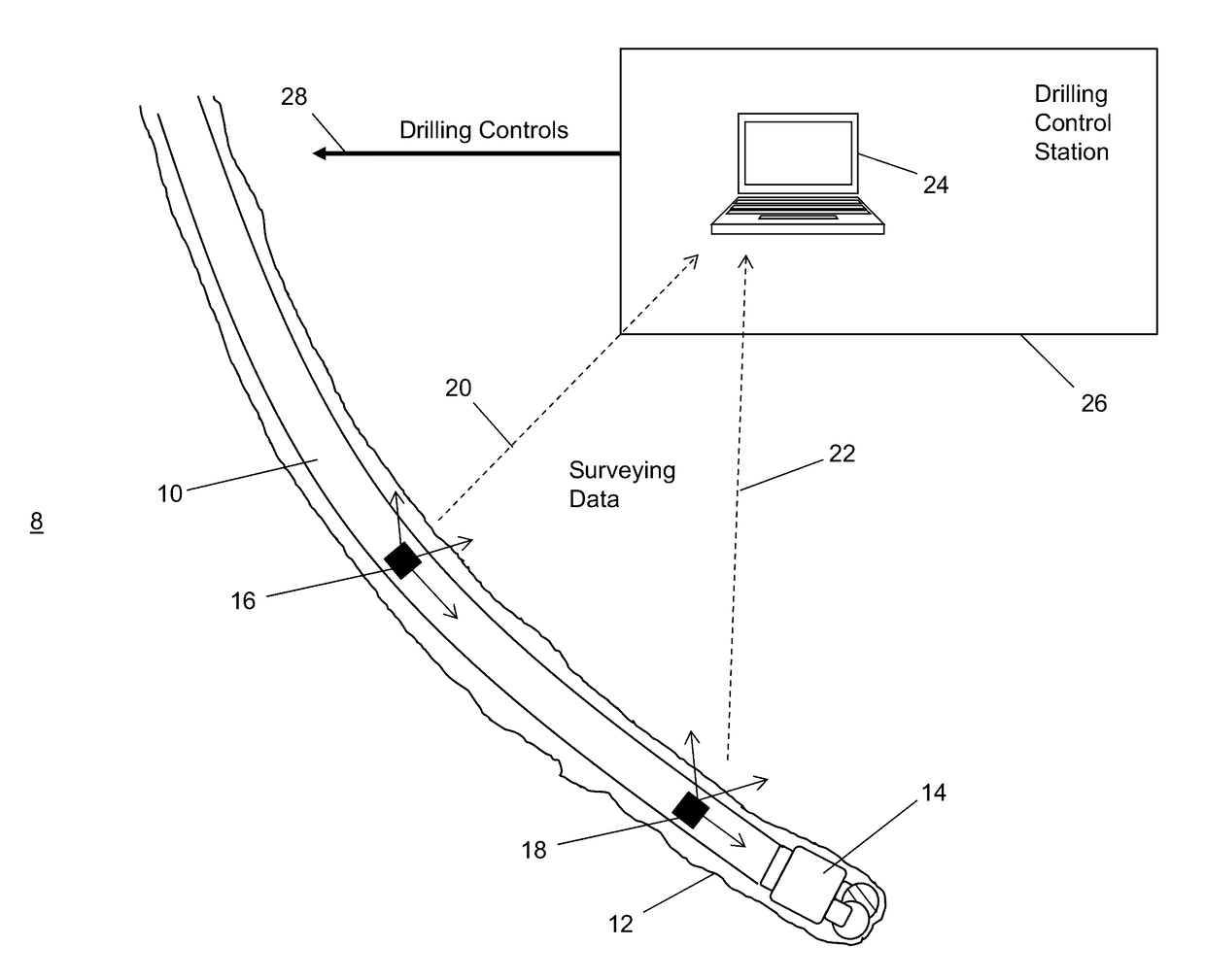
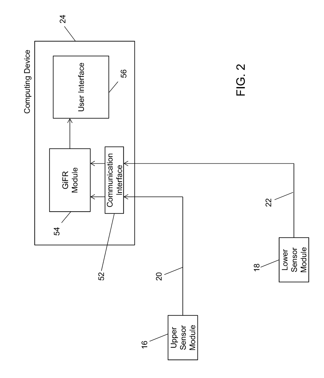
A system and method are provided for determining borehole azimuth. The method comprises receiving a first set of data from a first sensor module, the first sensor module comprising a first plurality of accelerometers; receiving a second set of data from a second sensor module, the second sensor module comprising a second plurality of accelerometers, the second sensor module being positioned further downhole than the first sensor module; determining a first set of gravity components using the first set of data and a second set of gravity components using the second set of data; determining a bend angle and a tilt angle using the first and second sets of gravity components; determining a change in azimuth using the bend and tilt angles; and providing an output indicative of the change in azimuth. The system and method may also use a crustal gravity vector to correct the computed azimuth.

Description

[0001]This application claims priority from U.S. Provisional Patent Application No. 61 / 908,409 filed on Nov. 25, 2013, the entire contents of which are incorporated herein by reference.TECHNICAL FIELD[0002]The following relates to systems and methods for determining a borehole azimuth using gravity in-field referencing.DESCRIPTION OF THE RELATED ART[0003]Directional drilling involves drilling a subterranean borehole along a particular path that, in at least part of its pathway, changes direction to provide at least one bend in the borehole. Subterranean boreholes are often surveyed to determine this particular path using sensor modules comprising magnetometers, gyroscopes, and / or accelerometers. The sensor modules are used to determine the gravity vector and the horizontal plane, as well as the orientation of the borehole longitudinal axis through the inclination and azimuth angles at a survey station. The inclination is the angle between the gravity vector and the projection of the...

Claims


Application Information

Patent Timeline
Patent Type & Authority Patents(United States)
IPC IPC(8): G01V7/00E21B47/024
CPCG01V7/00E21B47/024
Inventor KIM, JEONG WOOVARCOE, BRIAN E.PETROVIC, JOHN
Owner MOSTAR DIRECTIONAL TECH
Learn More