Wireless device and wireless control system

a wireless control system and wireless technology, applied in the direction of transmission systems, instruments, etc., to achieve the effect of excellent wireless control systems

Active Publication Date: 2017-04-18
SUMITOMO ELECTRIC IND LTD
View PDF11 Cites 0 Cited by
  • Summary
  • Abstract
  • Description
  • Claims
  • Application Information

AI Technical Summary

Benefits of technology

[0016]According to the present invention, an excellent wireless control system that utilizes energy harvesting can be provided.

Problems solved by technology

The at least one voltage generator is configured in a size that does not allow the voltage generator to generate sustainably-operating electric power when an attempt is made to directly drive the processor control unit.

Method used


Image

  • Wireless device and wireless control system
  • Wireless device and wireless control system
  • Wireless device and wireless control system

Examples


first embodiment

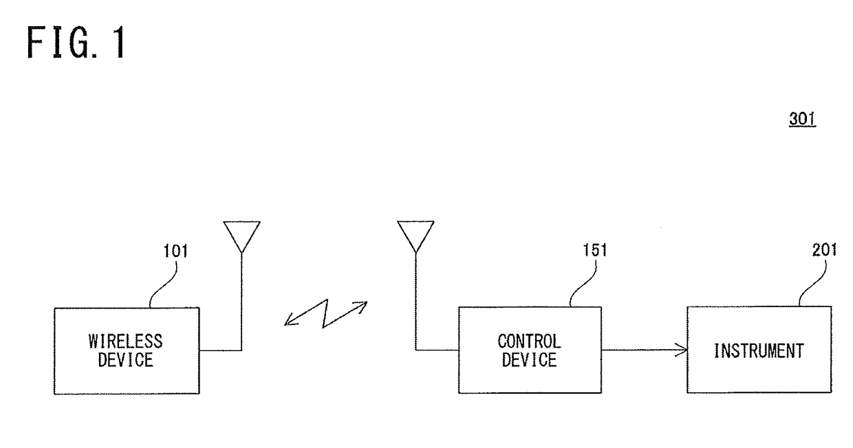
[0043]FIG. 1 is a diagram illustrating a configuration of a wireless control system according to the embodiment of the present invention.

[0044]Referring to FIG. 1 a wireless control system 301 includes a wireless device 101 and a control device 151.

[0045]The wireless device 101 transmits a wireless signal to the control device 151 in accordance with user's operation. In addition, for example, the wireless device 101 receives a wireless signal transmitted from the control device 151.

[0046]The control device 151 receives the wireless signal transmitted from the wireless device 101, and, for example, controls an instrument 201 based on the information included in the received wireless signal. The control device 151 may be configured to include the instrument 201 that is an object to be controlled.

[0047]Alternatively, the control device 151 may be configured to receive a wireless signal transmitted from the wireless device 101, generate some information from the information included in ...

second embodiment

[0121]In the first embodiment, the wireless device 101 executes the authentication process by using reference information. However, the control device 151 on the receiving side may perform this process. Hereinafter, the content of a second embodiment will be described.

[0122]In a wireless control system according to the second embodiment, the wireless device 101 has identification information, and transmits a wireless signal. The control device 151 receives the wireless signal from the wireless device 101, and performs the process based on the identification information included in the received wireless signal.

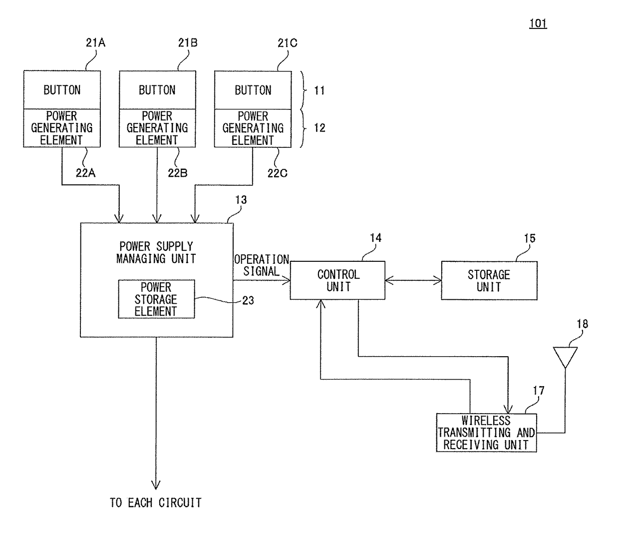
[0123]In the wireless device 101, when the operation on the operation unit 11 satisfies a predetermined condition, the control unit 14 transits to the transmission permission state in which transmitting the wireless signal including the content of the operation signal and the identification information stored in the storage unit 15 to the control device 151 is permitted. The co...


PUM


Abstract

A wireless device 101 is a wireless device having identification information, and includes: an operation unit 11; a power generating unit 12 that generates electric power by operation on the operation unit 11; a signal generating unit 13 that operates by using the electric power generated by the power generating unit 12 and is capable of outputting a signal of a kind corresponding to the content of each operation on the operation unit 11; a storage unit 15 that operates by using the electric power generated by the power generating unit 12 and nonvolatilely stores the content of an output signal of the signal generating unit 13, the identification information, and reference information; and a transmission control unit 14 that compares the content of the output signal with the reference information when the operation on the operation unit 11 satisfies a predetermined condition, the content of the output signal and the reference information being stored in the storage unit 15, and transits to a transmission permission state in which transmitting a wireless signal including the identification information stored in the storage unit 15 to a different device is permitted when a result of the comparison satisfies a predetermined condition.

Description

TECHNICAL FIELD[0001]The present invention relates to a wireless device and a wireless control system, and particularly relates to a wireless device and a wireless control system that utilize energy harvesting.BACKGROUND ART[0002]There has been developed an instrument that operates by using electric power generated by energy harvesting for harvesting minute energy from a surrounding environment such as light, heat, and oscillation.[0003]For example, Japanese Patent Publication No. 4824277 (Patent Literature 1) discloses the following technique.[0004]That is, a sensor system includes: at least one voltage generator that converts nonelectric energy into electric energy; at least one energy storage unit connected to a back position of the voltage generator; at least one voltage converter connected to the energy storage unit so that an output signal of the self matches the operation performed by a processor control unit; at least one sensor; and at least one transmission unit that perfo...

Claims


Application Information

Patent Timeline
Patent Type & Authority Patents(United States)
IPC IPC(8): G08C17/02
CPCG08C17/02G08C2201/11G08C2201/112
Inventor TEKI, SEIHIRAKAWA, MITSURU
Owner SUMITOMO ELECTRIC IND LTD
Why Eureka
Try Eureka