Maintenance system for technical research service

A maintenance system and technology research technology, applied in the field of box girder maintenance equipment, can solve the problems of large amount of dismantling construction, large amount of box girder engineering, uneven spraying, etc., to achieve the effect of ensuring quality

Inactive Publication Date: 2018-05-29
天津津嘉升溢生物科技有限公司
View PDF3 Cites 0 Cited by
  • Summary
  • Abstract
  • Description
  • Claims
  • Application Information

AI Technical Summary

Problems solved by technology

The existing maintenance system is to lay water pipes on the entire periphery of the box girder, set nozzles on the water pipes, and perform maintenance by spraying water on the box girder. However, it is inconvenient to lay water pipes inside the outer flange plate of the box girder and at the end of the bottom beam of the bottom plate. , without professional equipment; the laid water pipes are distributed on the entire outer surface of the box girder, the laying process is complicated, and the demolition also faces the problem of a large amount of construction, and the maintenance of the box girder requires a huge amount of work
The interior of the outer flange plate of the box girder and the bottom beam end of the bottom plate are usually sprayed directly by artificial water diversion pipes. The spraying is uneven during artificial spraying and maintenance, and the maintenance effect is not good.

Method used


Image

  • Maintenance system for technical research service
  • Maintenance system for technical research service
  • Maintenance system for technical research service

Examples


Embodiment

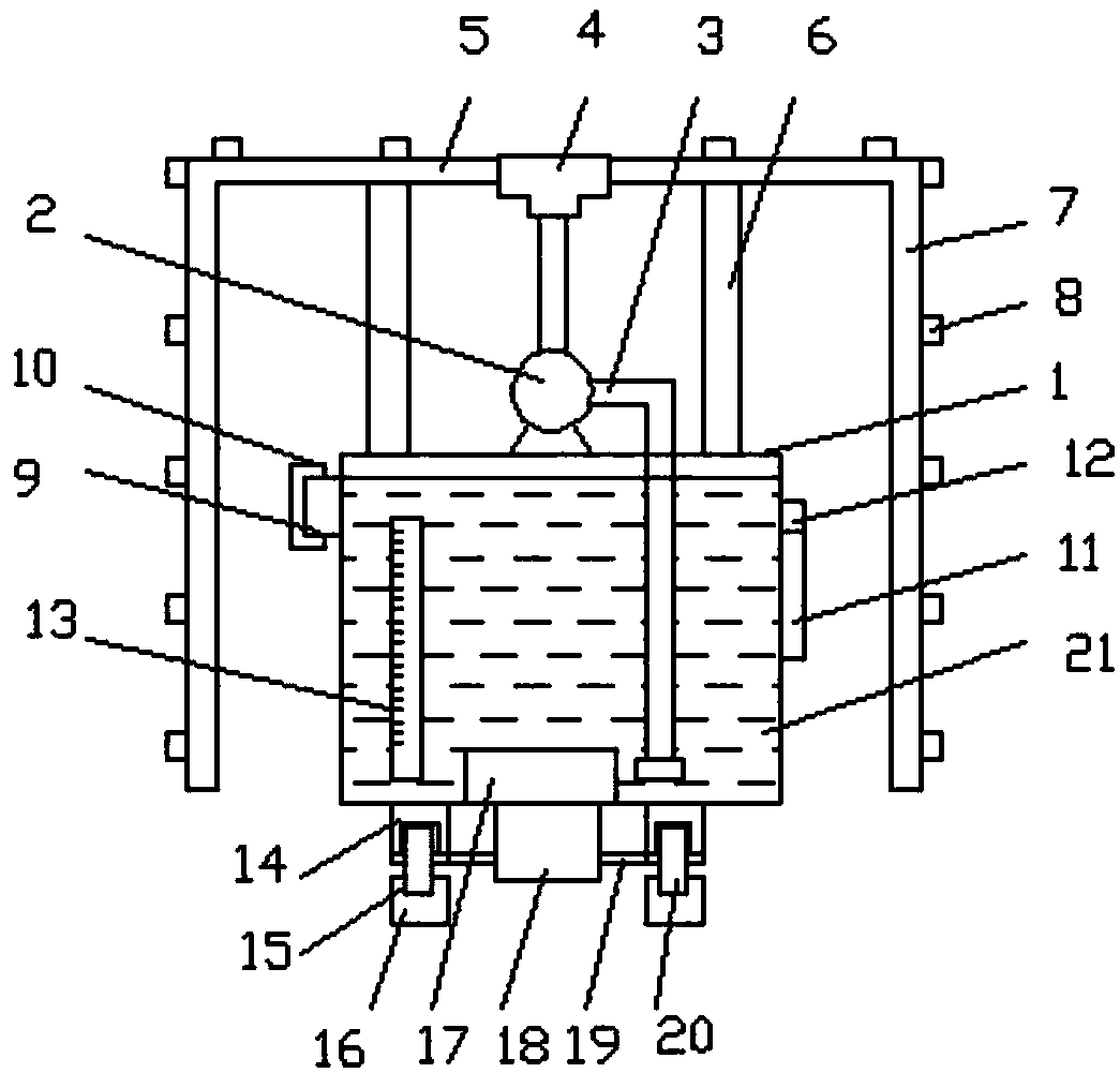
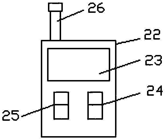
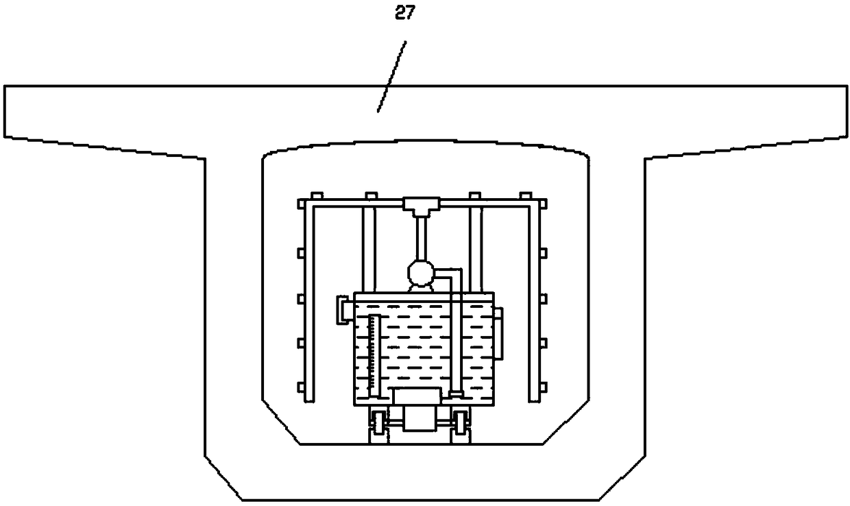
[0016] Example: see Figure 1-3 , a technical research service maintenance system of the present invention, comprising a box body 1 and a wireless controller 22, a water pump 2 is arranged on the upper side of the box body 1, water pipes 3 are arranged on both sides of the water pump 2, and one side of the water pipe 3 Connected with the box body 1 and extend into the bottom of the box body 1, the other end of the water pipe 3 is vertically connected with a three-way pipe 4, and the two sides of the three-way pipe 4 are connected with horizontal pipes 5, and the two sides of the horizontal pipe 5 The side is connected with a side pipe 7, and several nozzles 8 are arranged on the horizontal pipe 5 and the side pipe 7. The inside of the box 1 is provided with a maintenance water 21, and the lower side of the box 1 is provided with an iron support leg 14. , the lower side of the iron support leg 14 is provided with a walking wheel 20, the lower side of the box 1 is provided with ...


PUM


Abstract

The invention discloses a maintenance system for the technical research service. The maintenance system comprises a box body and a wireless controller. A water pump is arranged on the upper side of the box body. Water pipes are arranged on the two sides of the water pump. One side of each water pipe is connected with the box body and extends into the bottom of the box body. The other ends of the water pipes are vertically and upward connected with a tee. Transverse pipes are correspondingly connected to the two sides of the tee. Side pipes are connected to the two sides of each transverse pipe. Multiple spray heads are arranged on the transverse pipes and the side pipes. The box body is filled with maintenance water. Irony support legs are arranged on the lower side of the box body. Walking wheels are arranged on the lower sides of the irony support legs. A drive motor is arranged on the lower side of the box body. A drive shaft is arranged at the output end of the drive motor. By theadoption of the maintenance system for the technical research service, water can be sprayed to the positions, such as the beam ends of bottom layers of bottom plates and the interiors of frange platesof the outer sides of box beams, the water is evenly sprayed, the maintenance effect is guaranteed effectively, automatic spraying and maintenance can be achieved through wireless control, the operations are convenient and fast, and the quality of the prefabricated box beams is guaranteed.

Description

technical field [0001] The invention relates to a box girder maintenance system, in particular to a technical research service maintenance system, which belongs to the technical field of box girder maintenance equipment. Background technique [0002] In the process of box girder production, concrete curing can not only accelerate the growth of concrete strength, but also prevent premature evaporation of water and produce large shrinkage deformation and dry shrinkage cracks. Therefore, the maintenance of the initial stage after concrete pouring is very important. The curing should be carried out immediately after the final setting of the concrete, and the curing should be carried out immediately after the pouring is completed. The existing maintenance system is to lay water pipes on the entire periphery of the box girder, set nozzles on the water pipes, and perform maintenance by spraying water on the box girder. However, it is inconvenient to lay water pipes inside the outer...

Claims


Application Information

Patent Timeline
IPC IPC(8): B28B11/24
CPCB28B11/245
Inventor 薛颖
Owner 天津津嘉升溢生物科技有限公司
Why Eureka
Try Eureka