

Antenna device and communication terminal device
a technology of communication terminal and antenna device, which is applied in the direction of resonant antenna, resonant antenna, loop antenna with ferromagnetic core, etc., can solve the problems of increasing the number of man-hours required for production, and preventing communication with a counterpart antenna. , to achieve the effect of preventing the deterioration of the field shield effect and reducing the mechanical strength
- Summary
- Abstract
- Description
- Claims
- Application Information
AI Technical Summary
Benefits of technology
Problems solved by technology
Method used
Image

Examples
first preferred embodiment
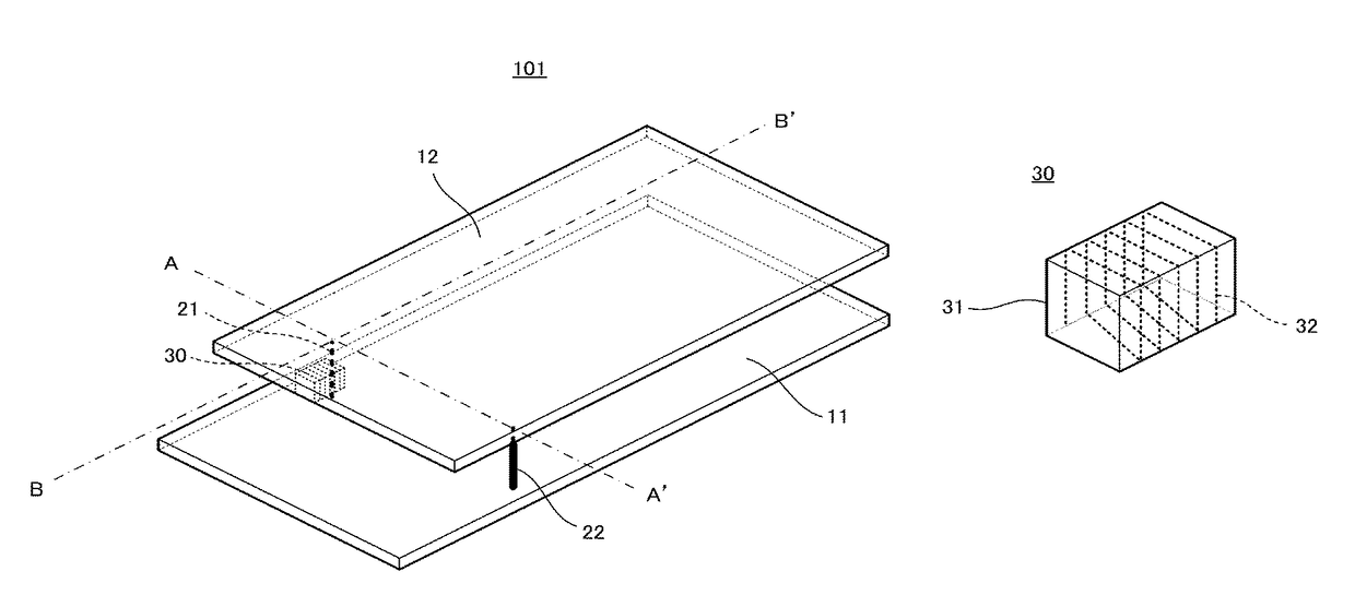
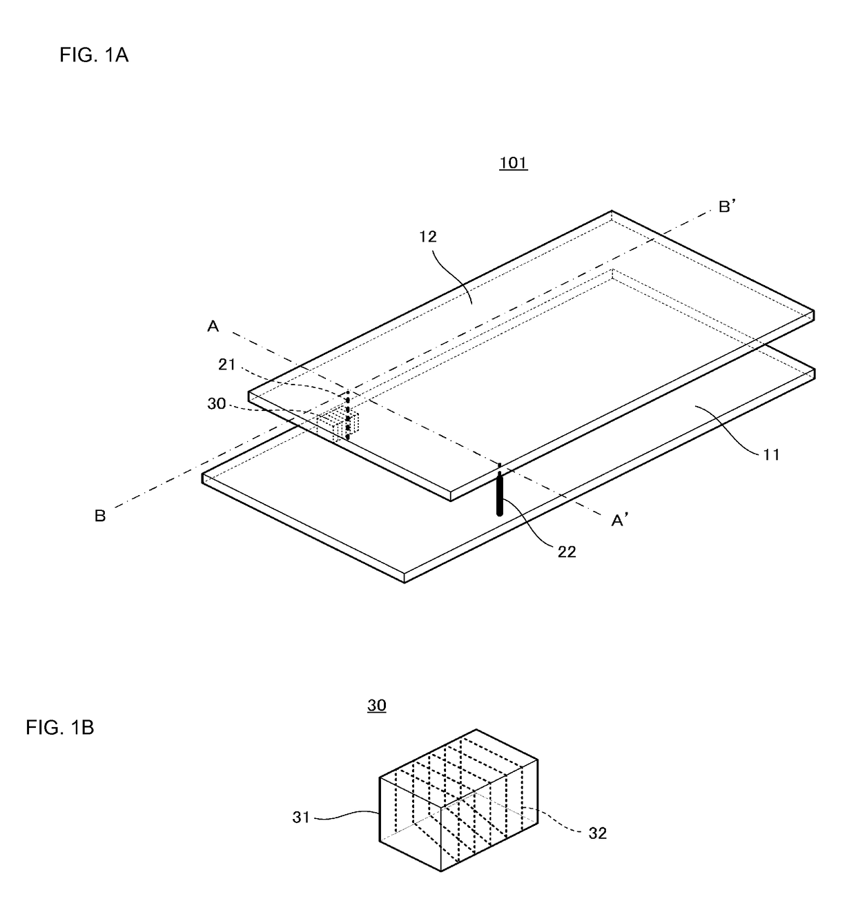
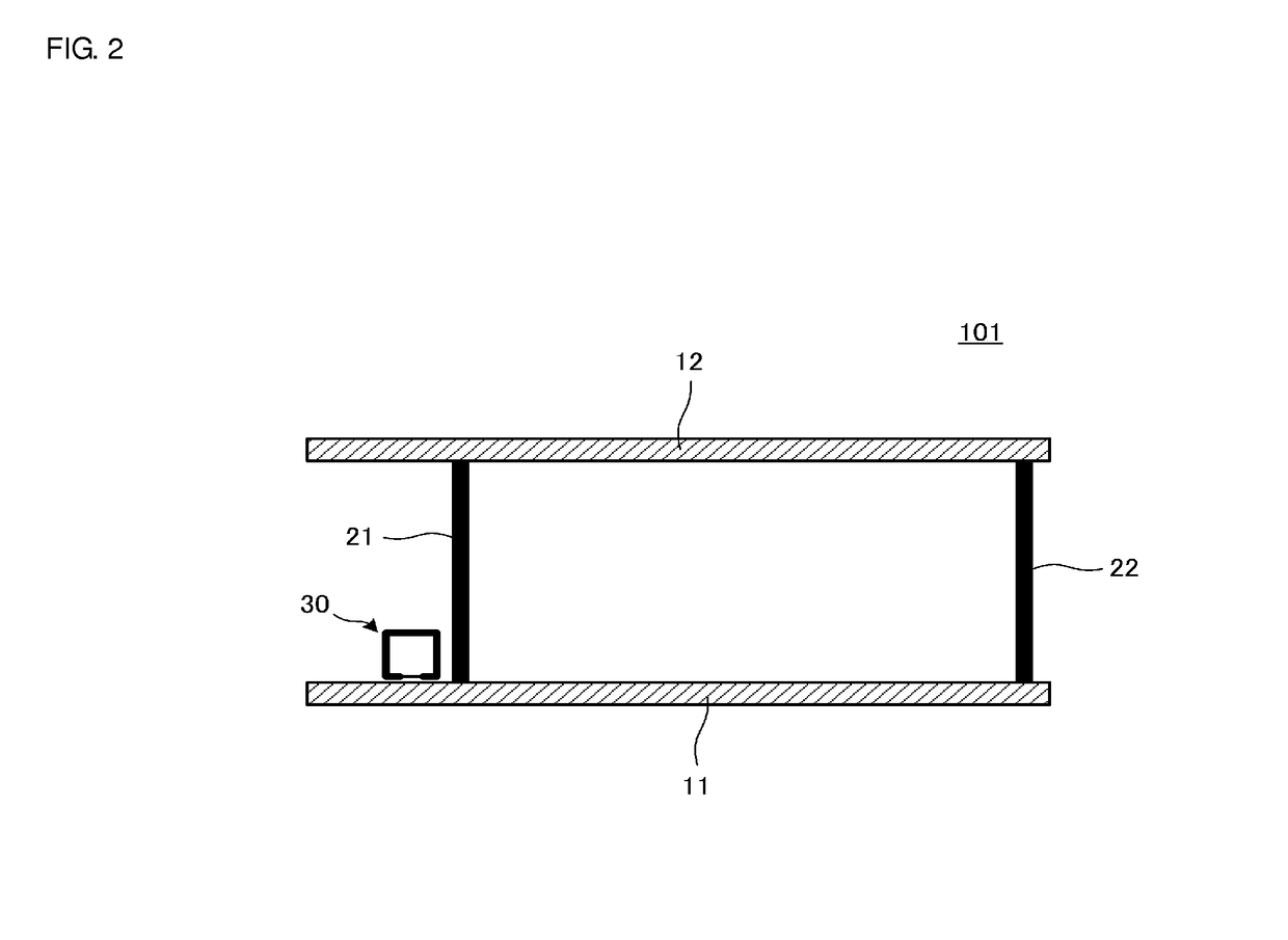
[0032]FIG. 1A is a perspective view of an antenna device 101 according to a first preferred embodiment of the present invention, and FIG. 1B is a perspective view of an antenna coil provided for the antenna device 101. FIG. 2 is a cross-sectional view taken along the line A-A′ in FIG. 1A. The antenna device 101 is preferably used for an HF band such as 13.56 MHz and is a proximity-type or vicinity-type antenna using electromagnetic (mainly magnetic) field coupling to a communication counterpart antenna, for example.
[0033]The antenna device 101 includes a first conductor surface 11 and a second conductor surface 12 that face each other and are spaced apart from each other. The first conductor surface 11 and the second conductor surface 12 are connected to each other through a first connecting conductor 21 and a second connecting conductor 22. The antenna coil 30 is located between the first conductor surface 11 and the second conductor surface 12 and in proximity to the first connect...
second preferred embodiment
[0044]FIG. 6 is a perspective view of an antenna device 102 according to a second preferred embodiment of the present invention. The antenna device 102 includes the first conductor surface 11 and the second conductor surface 12 that face each other. The first conductor surface 11 and the second conductor surface 12 are connected to each other through the first connecting conductor 21, the second connecting conductor 22, a third connecting conductor 23, and a fourth connecting conductor 24. The antenna coil 30 is located between the first conductor surface 11 and the second conductor surface 12 and in proximity to the first connecting conductor 21. In an example illustrated in FIG. 6, the connecting conductors 21 and 22 and the conductor surfaces 11 and 12 define a closed loop, the connecting conductors 21 and 23 and the conductor surfaces 11 and 12 define a closed loop, and the connecting conductors 21 and 24 and the conductor surfaces 11 and 12 define a closed loop. The antenna coi...
third preferred embodiment
[0046]FIG. 7A is a perspective view of a portion of a communication terminal device including an antenna device 103 according to a third preferred embodiment of the present invention. FIG. 7B is a perspective view of a portion of a communication terminal device including an antenna device in a comparative example. These communication terminal devices preferably are communication terminal devices each including an antenna 81 for the UHF band that is located in a circuit board. In the circuit board, a ground electrode that is the first conductor surface 11 is provided. In FIGS. 7A and 7B, the antenna 81 is an inverted-F antenna, but is schematically illustrated in the figures by using a conductor line. The antenna 81 for the UHF band is preferably used for calls and data communications by a mobile phone.
[0047]In the antenna device 103 in the present preferred embodiment illustrated in FIG. 7A, the first connecting conductor 21 is located inward of the edges of the first conductor surf...
PUM
 Abstract
Description
Claims
Application Information