
System analysis device, system analysis method and system analysis program

a system analysis and program technology, applied in the field of system analysis devices, system analysis methods, and programs, to achieve the effect of high accuracy

Active Publication Date: 2017-05-23
NEC CORP
View PDF11 Cites 24 Cited by
  • Summary
  • Abstract
  • Description
  • Claims
  • Application Information

AI Technical Summary

Benefits of technology

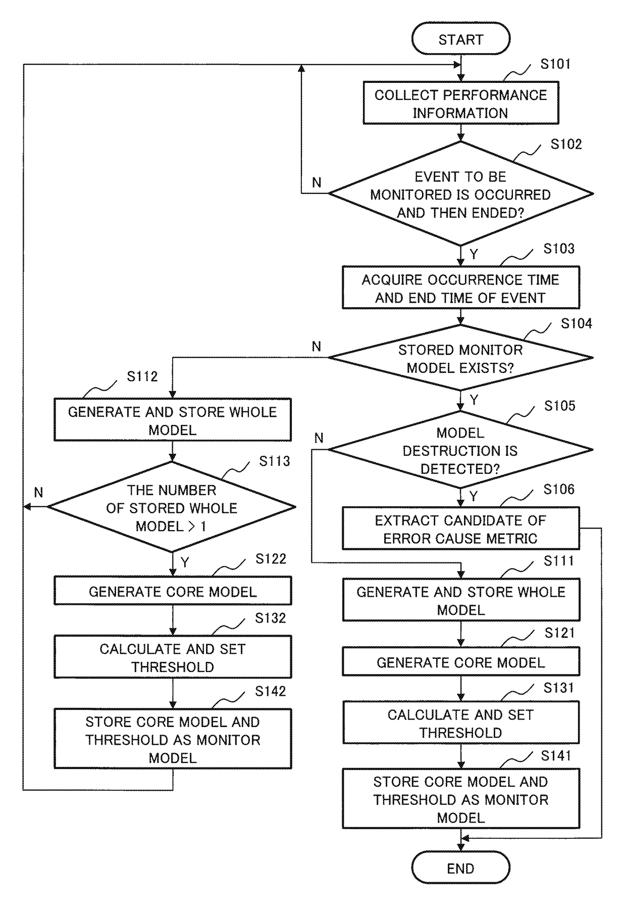
[0017]According to the present invention, it is possible to perform error determination of a system by monitoring an event having low occurrence frequency with high accuracy.

Problems solved by technology

A case in which a prediction error exceeds a threshold value at the time of monitoring is correlation destruction, and indicates occurrence of an error.

Method used


Image

  • System analysis device, system analysis method and system analysis program
  • System analysis device, system analysis method and system analysis program
  • System analysis device, system analysis method and system analysis program

Examples


Embodiment Construction

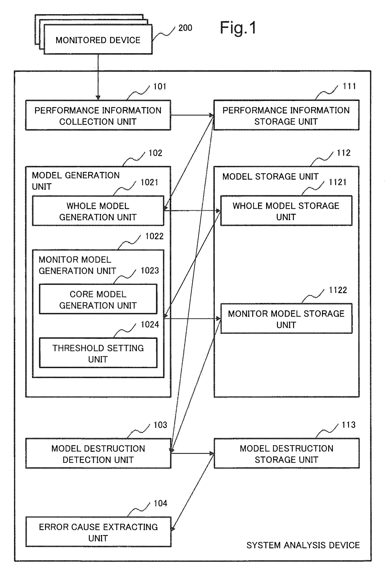
[0028]The exemplary embodiment of the present invention will be described with reference to drawings. In the present exemplary embodiment, as an example, an application to error detection of an IT (Information Technology) system is described. In the present exemplary embodiment, it is assumed that an event to be monitored is one type. When there is a plurality of types of events to be monitored, the operations of the present exemplary embodiment are required to be performed in parallel for respective events.

[0029]The configuration of the system analysis device according to the present exemplary embodiment will be described. FIG. 1 is a block diagram illustrating a configuration of a system analysis device 100 according to the exemplary embodiment.

[0030]As illustrated in FIG. 1, the system analysis device 100 of the present exemplary embodiment is connected with a monitored system which includes one or more monitored devices 200. The monitored devices 200 are devices which constitute...


PUM


Abstract

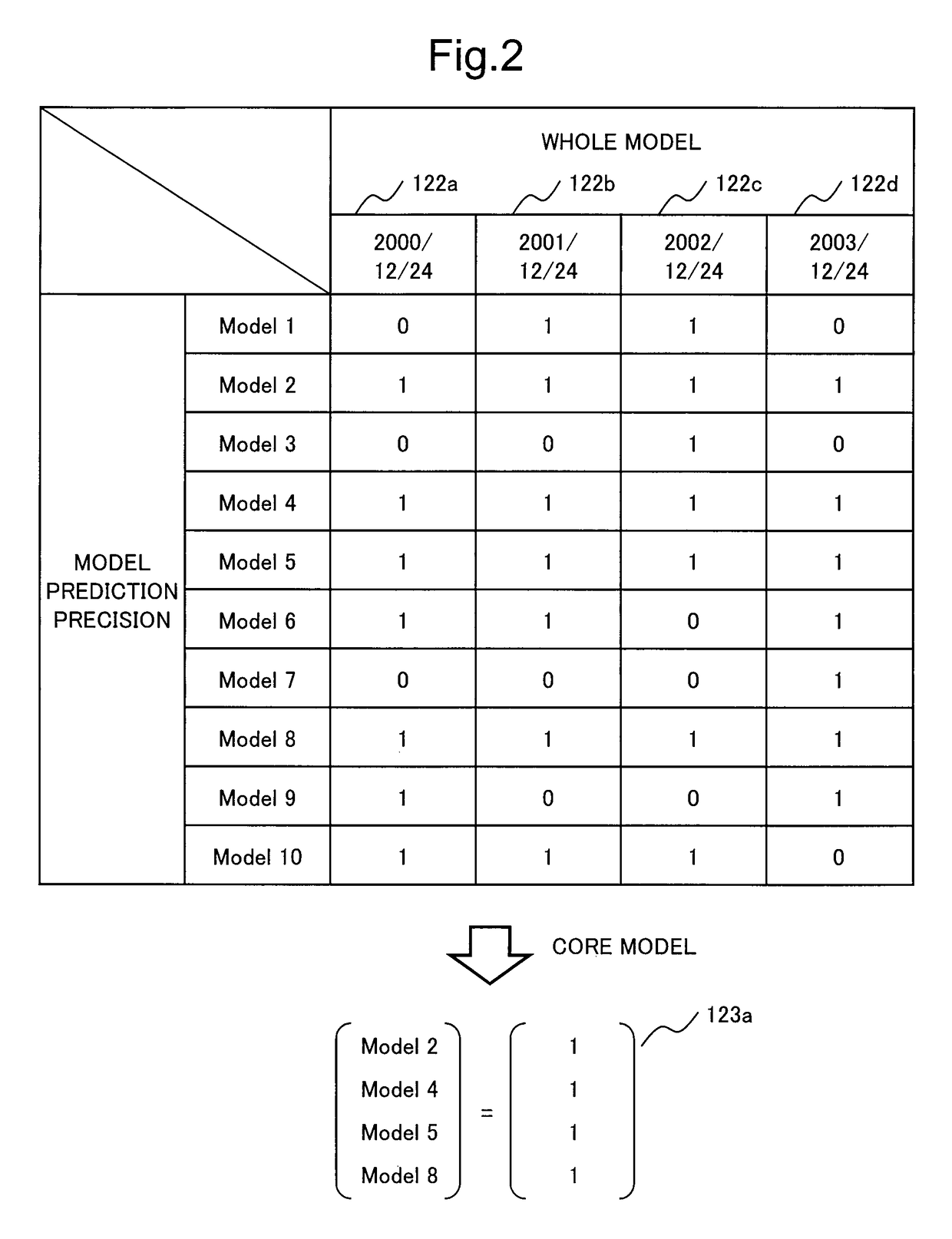
A system analysis device 100 includes a whole model generation unit 1021 which generates a whole model which is obtained by modeling elements or whole of a system and which includes a plurality of partial models, a core model generation unit 1023 which extracts, from a plurality of whole models generated on the basis of the same event, the partial models whose prediction precision satisfies a predetermined criteria, and generates a core model by integrating the extracted partial models, and a threshold setting unit 1024 which calculates a distance between the core model and the plurality of whole models using a predetermined definition, and outputs the distance as a threshold value for error determination using the core model.

Description

[0001]This application is a National Stage Entry of PCT / JP2014 / 002842 filed on May 29, 2014, which claims priority from Japanese Patent Application 2013-132226 filed on Jun. 25, 2013, 2013-175176 filed on Aug. 27, 2013, the contents of all of which are incorporated herein by reference, in their entirety.TECHNICAL FIELD[0002]The present invention relates to a system analysis device, a system analysis method, and a program, for analyzing a failure, an error, and the like of a system.BACKGROUND ART[0003]PTL 1 describes an example of an operation management system which models a system using time series information on system performance and determines a cause of a failure or an error of the system using the generated model.[0004]The operation management system described in PTL 1 generates a correlation model of a system by determining a correlation function representing correlation for each pair of a plurality of metrics on the basis of measurement values of the plurality of metrics of ...

Claims


Application Information

Patent Timeline
Patent Type & Authority Patents(United States)
IPC IPC(8): G06F11/00G06F11/34G06N7/00G06F11/07G06N99/00
CPCG06F11/079G06F11/0751G06F11/34G06F11/3409G06F11/3447G06N7/005G06N99/005G06F11/0748G06F11/0754G06N20/00G06N7/01
Inventor YOSHINAGA, NAOKINATSUMEDA, MASANAO
Owner NEC CORP
Learn More