Ultrasonic transducer

a transducer and ultrasonic technology, applied in the field of ultrasonic transducers, can solve the problems of inability to use ultrasonic transducers with poor temperature-sound pressure characteristics, inability to reduce output sound pressure, etc., and achieve excellent temperature-sound pressure characteristics and increase output sound pressure.

Active Publication Date: 2017-05-30
MURATA MFG CO LTD
View PDF8 Cites 34 Cited by
  • Summary
  • Abstract
  • Description
  • Claims
  • Application Information

AI Technical Summary

Benefits of technology

[0010]A configuration may be adopted in which the ultrasonic wave generator is composed of a first piezoelectric vibrator having a plate-like shape and bonded to one main surface of a frame and a second piezoelectric vibrator having a plate-like shape and bonded to another main surface of the frame, the first piezoelectric vibrator and the second piezoelectric vibrator are driven in a buckling tuning fork vibration mode in which they vibrate with opposite phases to each other at the same frequency, and the acoustic path includes a first acoustic path that extends from the first piezoelectric vibrator to the ultrasonic wave emission hole and a second acoustic path that extends from the second piezoelectric vibrator to the ultrasonic wave emission hole. With this configuration, resonance of air in the first acoustic path and resonance of air in the second acoustic path are superposed with each other and output and therefore the output sound pressure can be increased.
[0011]In the ultrasonic transducer of the present invention having the above-described configuration, the piezoelectric vibrator is driven at a driving frequency at which a temperature-sound pressure characteristic for resonance of air and a temperature-amplitude characteristic at the driving frequency of the piezoelectric vibrator have opposite tendencies and therefore the ultrasonic transducer has a very excellent temperature-sound pressure characteristic. Consequently, the ultrasonic transducer of the present invention can exhibit a staple output sound pressure over a wide temperature range.

Problems solved by technology

This is because even if a sufficient output sound pressure is provided at a certain temperature, the output sound pressure may decrease when the temperature changes and an ultrasonic wave may no longer arrive at the target and as a result the applications in which such ultrasonic transducers can be used is limited.
For example, it has not been possible to use an ultrasonic transducer having a poor temperature-sound pressure characteristic in a car-mounted ultrasonic sensor for distance measurement that has to be able to cope with a severe temperature environment.
However, in the ultrasonic transducer 400, since measures have not been taken with respect to temperature characteristics of the resonant frequency, mechanical quality coefficient (Qm), electrostatic capacity, piezoelectric constant (d constant) and so forth of the piezoelectric vibrator 103 itself, significant improvements in the temperature-sound pressure characteristic have not been achieved.

Method used


Image

  • Ultrasonic transducer
  • Ultrasonic transducer
  • Ultrasonic transducer

Examples


first embodiment

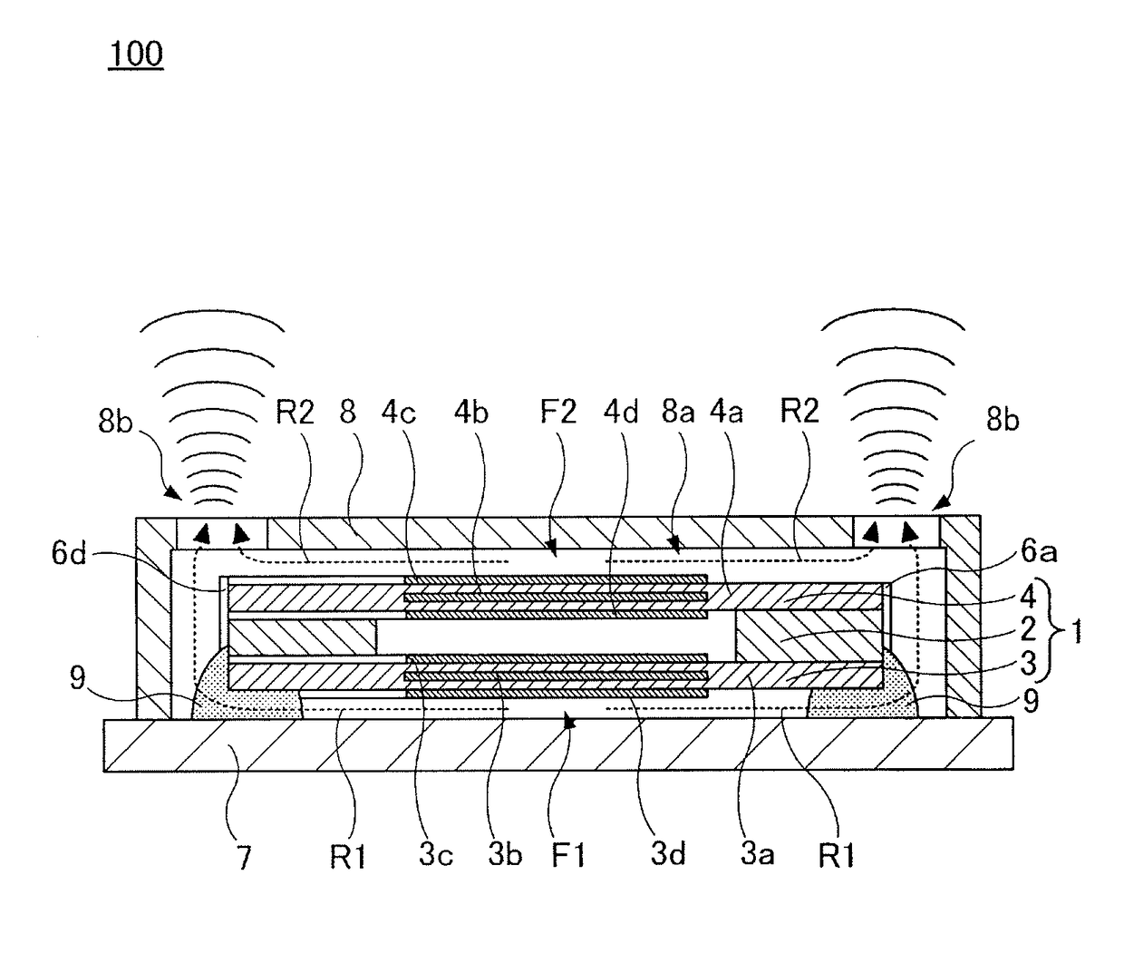
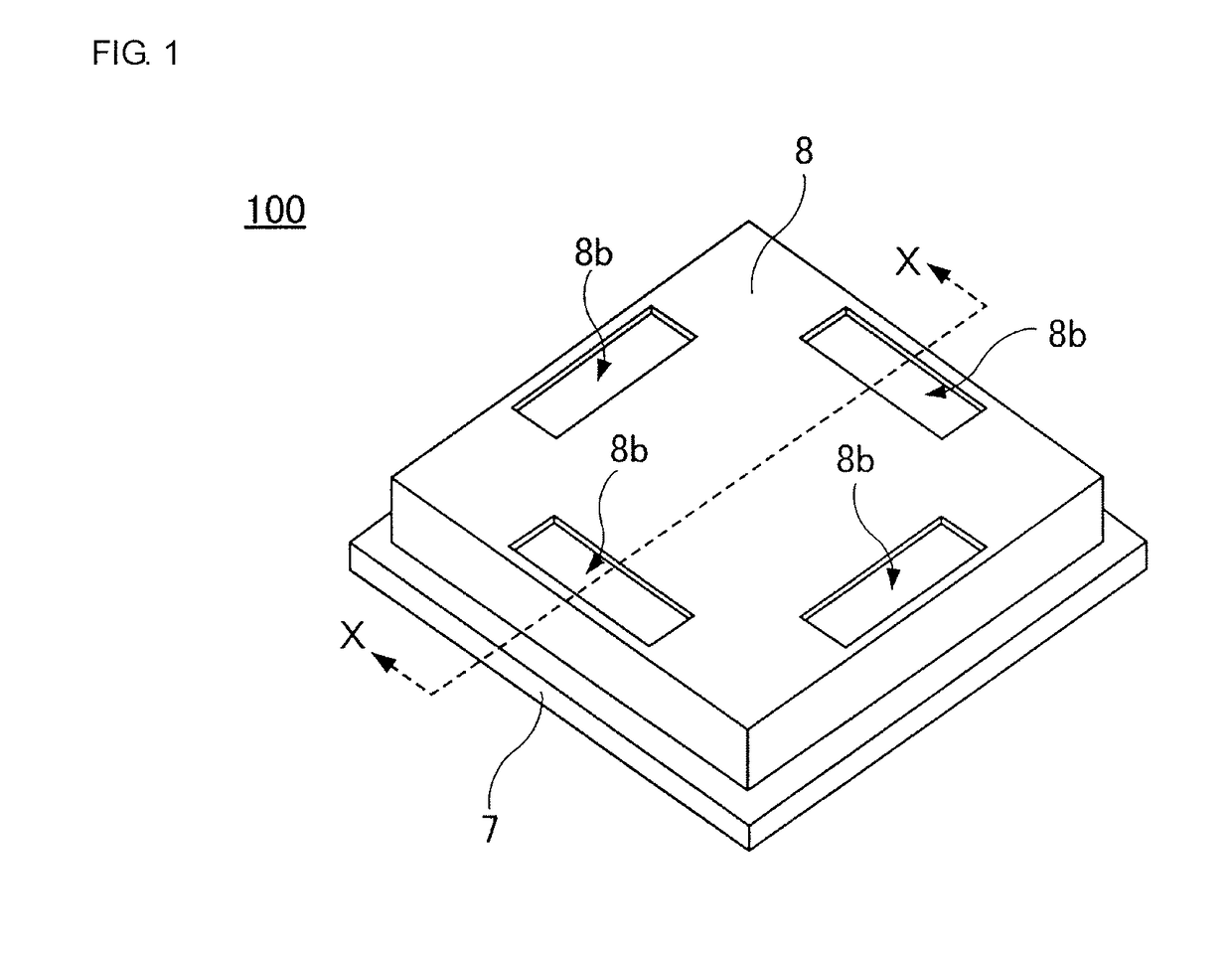
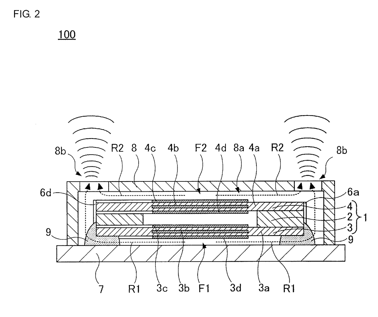
[0029]An ultrasonic transducer 100 according to a first embodiment of the present invention is illustrated in FIG. 1 and FIG. 2. Here, FIG. 1 is a perspective view, and FIG. 2 is a sectional view of a portion taken along the chain line X-X in FIG. 1. In addition, an ultrasonic wave generator 1 employed in the ultrasonic transducer 100 is illustrated in FIG. 3. Here, FIG. 3 is an exploded perspective view.

[0030]The ultrasonic transducer 100 includes the ultrasonic wave generator 1.

[0031]The ultrasonic wave generator 1 includes a frame 2, a first piezoelectric vibrator 3 and a second piezoelectric vibrator 4. The frame 2 has a through hole 2a with a diameter on the order of 2.4 mm formed in a center portion thereof and is composed of for example a ceramic body with a thickness on the order of 200 μm. The ultrasonic wave generator 1 has a square planar shape with sides with a length of 2.8 mm and has a thickness of 0.32 mm.

[0032]The first piezoelectric vibrator 3, which is a bimorph-ty...

second embodiment

[0067]An ultrasonic transducer 200 according to a second embodiment of the present invention is illustrated in FIG. 14. FIG. 14 is a sectional view.

[0068]In the above-described ultrasonic transducer 100 of the first embodiment, the ultrasonic wave generator 1, which includes the first piezoelectric vibrator 3 and the second piezoelectric vibrator 4, is used as an ultrasonic wave generator, whereas, in the ultrasonic transducer 200 of the present embodiment, an ultrasonic wave generator 11 having a single piezoelectric vibrator 13 is used as an ultrasonic wave generator.

[0069]The ultrasonic transducer 200 includes the ultrasonic wave generator 11 and a case composed of a base member 17 composed of for example a glass epoxy and a cover member 18 composed of for example nickel silver. The ultrasonic wave generator 11 includes a pedestal 12 and the piezoelectric vibrator 13.

[0070]The pedestal 12 is a frame having a through hole formed in a center portion thereof. The piezoelectric vibra...

third embodiment

[0076]An ultrasonic transducer 300 according to a third embodiment of the present invention is illustrated in FIG. 15. FIG. 15 is a sectional view.

[0077]In the above-described ultrasonic transducer 100 of the first embodiment, the ultrasonic wave generator 1, which includes the first piezoelectric vibrator 3 and the second piezoelectric vibrator 4, is used as an ultrasonic wave generator, whereas in the ultrasonic transducer 300 of the present embodiment, an ultrasonic wave generator 21 having a single piezoelectric vibrator 23 is used as an ultrasonic wave generator.

[0078]The ultrasonic transducer 300 includes the ultrasonic wave generator 21 and a case composed of a base member 27 composed of for example a glass epoxy and a cover member 28 composed of for example nickel silver. The ultrasonic wave generator 21 includes a cavity 22 and the piezoelectric vibrator 23.

[0079]A concavity 22a is formed in the cavity 22. The piezoelectric vibrator 23, which is a bimorph-type piezoelectric...


PUM


Abstract

An ultrasonic transducer is provided that includes an ultrasonic wave generator having piezoelectric vibrators, and cases having ultrasonic wave emission holes and accommodating the ultrasonic wave generator. Acoustic paths in which air serves as a medium are formed by the ultrasonic wave generator and the and extend from the piezoelectric vibrators to the ultrasonic wave emission holes. Resonance of air is generated in the acoustic paths by ultrasonic waves generated by the piezoelectric vibrators in which the ultrasonic wave emission holes are open ends of the resonance. The piezoelectric vibrators are driven at a driving frequency at which the temperature-sound pressure characteristic for the resonance of air and the temperature-amplitude characteristic at the driving frequency of the piezoelectric vibrators have opposite tendencies.

Description

CROSS-REFERENCE TO RELATED APPLICATIONS[0001]The present application is a continuation of PCT / JP2012 / 068666 filed Jul. 24, 2012, which claims priority to Japanese Patent Application No. 2011-170230, filed Aug. 3, 2011, the entire contents of each of which are incorporated herein by reference.FIELD OF THE INVENTION[0002]The present invention relates to ultrasonic transducers and more specifically relates to ultrasonic transducers that have an excellent temperature-sound pressure characteristic.BACKGROUND OF THE INVENTION[0003]The temperature-sound pressure characteristic is extremely important in ultrasonic transducers used in ultrasonic sensors and so forth. This is because even if a sufficient output sound pressure is provided at a certain temperature, the output sound pressure may decrease when the temperature changes and an ultrasonic wave may no longer arrive at the target and as a result the applications in which such ultrasonic transducers can be used is limited. For example, ...

Claims


Application Information

Patent Timeline
Patent Type & Authority Patents(United States)
IPC IPC(8): B06B1/06G10K9/22G10K9/122G10K11/00H01L41/047
CPCB06B1/0607B06B1/0603G10K9/122G10K9/22G10K11/004H01L41/047H10N30/87
Inventor YAMAMOTO, HIRONARIMITANI, AKIHIRO
Owner MURATA MFG CO LTD
Why Eureka
Try Eureka