mems piezoelectric speaker

A piezoelectric speaker, speaker technology, applied in electrostatic transducer speakers, microphones, piezoelectric/electrostrictive transducers, etc., can solve the problems of small size and speaker performance constraints, achieve large effective length, improve vibration Amplitude, the effect of increasing the output sound pressure

Active Publication Date: 2021-12-24
ROFS MICROSYST TIANJIN CO LTD
View PDF20 Cites 0 Cited by
  • Summary
  • Abstract
  • Description
  • Claims
  • Application Information

AI Technical Summary

Problems solved by technology

Due to the small size, the performance (such as output sound pressure) of the speaker is limited to some extent

Method used


Image

  • mems piezoelectric speaker
  • mems piezoelectric speaker
  • mems piezoelectric speaker

Examples


Embodiment Construction

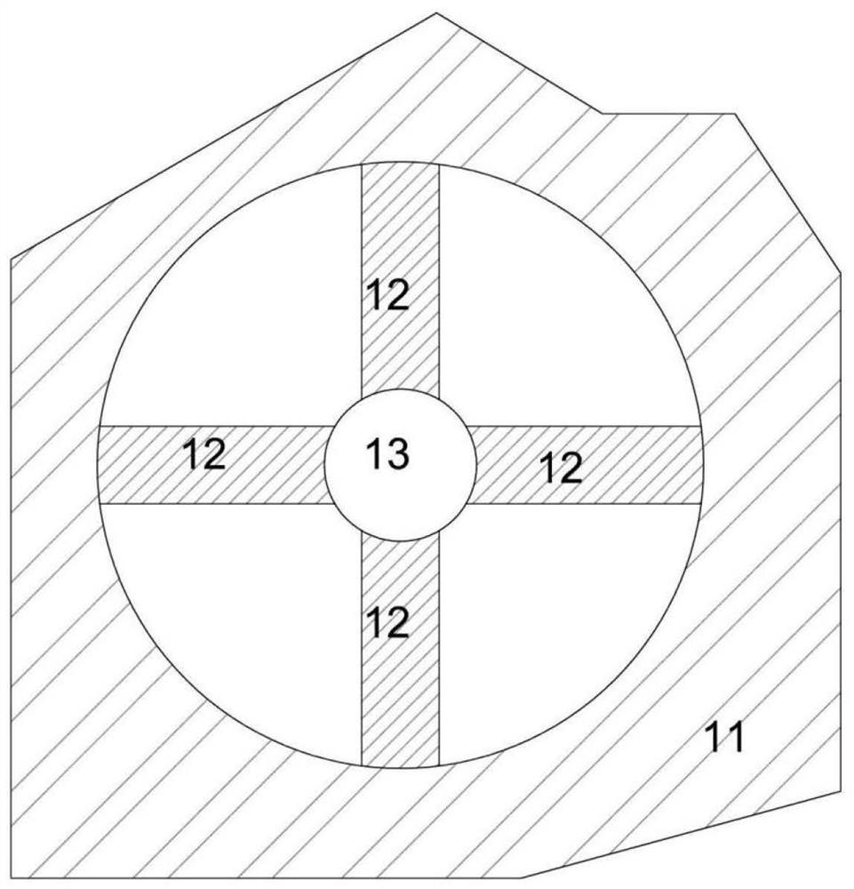
[0064] figure 1 In the MEMS speaker in the prior art shown, its load plate 13 is located on the extension line of the strip branch of the actuator 12. According to this layout, in the case of a certain overall area of ​​the speaker, if the length of the actuator branch is to be guaranteed , the area of ​​the load plate is affected. If the area of ​​the load plate is to be increased, the length of the actuator branch needs to be shortened. Therefore, this layout cannot take into account the area of ​​the load plate and the length of the actuator branch, which affects the output sound pressure of the speaker. On the other hand, the simple rectangular shape of the actuator leads to its low equivalent bending flexibility, which is reflected in the small maximum displacement of the actuator (that is, the limited displacement of the load plate), which ultimately affects the maximum outputtable sound pressure of the speaker.

[0065] In the embodiment of the present invention, relat...


PUM


Abstract

The invention provides a MEMS piezoelectric loudspeaker, including a load plate and an actuator, the load plate is polygonal, circular, or elliptical, and each branch of the actuator is strip-shaped and arranged along the extending direction of the edge of the load plate. According to the technical scheme of the invention, the space inside the loudspeaker is effectively utilized, the actuator has a larger effective length, the vibration amplitude of the load plate is increased, and the output sound pressure of the loudspeaker is increased.

Description

technical field [0001] The invention relates to a MEMS piezoelectric speaker. Background technique [0002] Micro speakers are currently widely used in various miniaturized and miniaturized acoustic devices and electronic equipment, and are used in multimedia and electronic entertainment equipment. The MEMS actuator is an important part of the above speaker, and its core working principle is to use piezoelectric materials to realize the coupling and mutual conversion of acoustic energy (mechanical energy) and electrical energy. Such as figure 1 as shown, figure 1 It is a schematic diagram of the energy conversion structure of the MEMS loudspeaker according to the prior art, which shows four branches of the MEMS actuator 12 arranged in the frame 11 (usually made of silicon material), and connected to the four branches The load tray 13 at one end of the branch. The actuator 12 realizes the coupling of sound energy and electric energy, and the load plate 13 is used to condu...

Claims


Application Information

Patent Timeline
Patent Type & Authority Patents(China)
IPC IPC(8): H04R19/02H04R17/00
CPCH04R19/02H04R17/00H04R2201/003
Inventor 张孟伦庞慰A·A·杜拉尼
Owner ROFS MICROSYST TIANJIN CO LTD
Why Eureka
Try Eureka