Ultrasonic generator

a generator and ultrasonic technology, applied in the field of ultrasonic generators, can solve the problems of limiting the extent of polarization of the piezoelectric vibrator, the limitation of the output sound pressure, and the limitation of the fracture limit, so as to achieve the effect of increasing the output sound pressur

Active Publication Date: 2017-12-26
MURATA MFG CO LTD
View PDF18 Cites 0 Cited by
  • Summary
  • Abstract
  • Description
  • Claims
  • Application Information

AI Technical Summary

Benefits of technology

[0009]An object of the present invention is to provide an ultrasonic generator that is capable of further increasing output sound pressure.
[0012]In another particular aspect of the ultrasonic generator according to the present invention, the ultrasonic generator further includes a second supporting member that is provided between the ultrasonic generating element and the second case member and that supports the ultrasonic generating element so that a space is formed between a top surface of the ultrasonic generating element and a bottom surface of the second case member. The second supporting member is provided so that, in a second acoustic path that includes the space formed between the top surface of the ultrasonic generating element and the bottom surface of the second case member and that extends to the sound-wave emission hole from the sound pressure generation center point of the ultrasonic generating element, a transverse section of the acoustic path has a portion that becomes smaller than another portion thereof. In this case, it is possible to effectively increase sound pressure in both the first and second acoustic paths.
[0017]In the ultrasonic generator according to the present invention, the first supporting member is provided so that, in the first acoustic path that includes the space formed between the bottom surface of the ultrasonic generating element and the top surface of the first case member and that extends to the sound-wave emission hole from the sound pressure generation center point of the ultrasonic generating element, the transverse section of the acoustic path has a portion that becomes smaller than another portion thereof. Therefore, it is possible to effectively increase output sound pressure.

Problems solved by technology

However, in the existing ultrasonic generator 500, there is a limit to how high the output sound pressure can be made.
However, there is a limit to the extent of polarization of the piezoelectric vibrator.
If the electric power supply is too large, the piezoelectric vibrator may exceed the fracture limitation.
Consequently, there is a limit to how high the output sound pressure can be made.

Method used


Image

  • Ultrasonic generator
  • Ultrasonic generator
  • Ultrasonic generator

Examples


Embodiment Construction

[0027]Specific embodiments of the present invention are hereunder described with reference to the drawings, so that the present invention is made explicit.

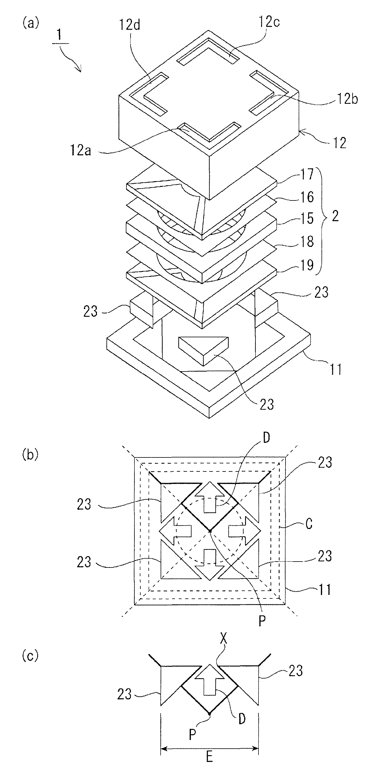
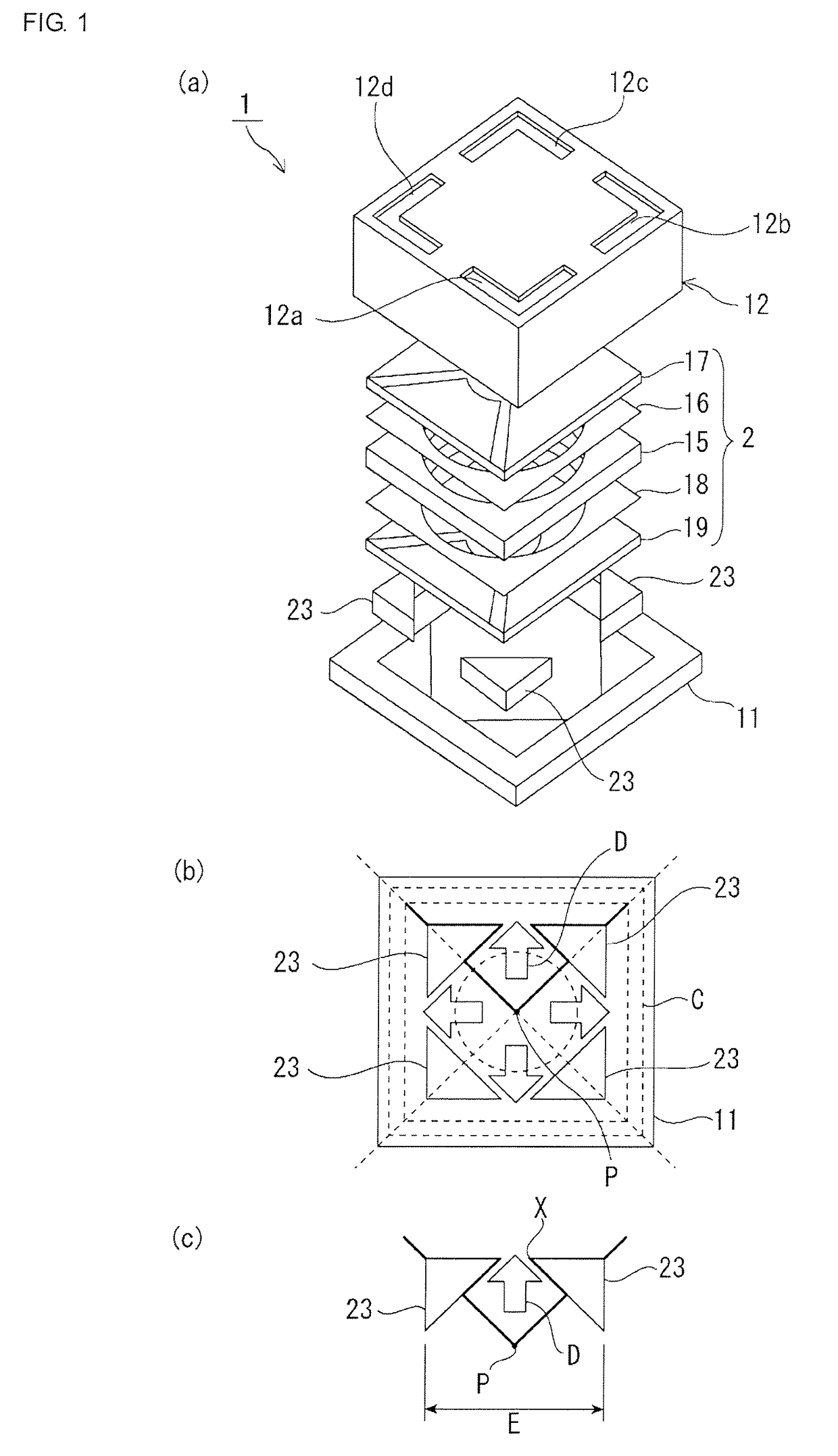
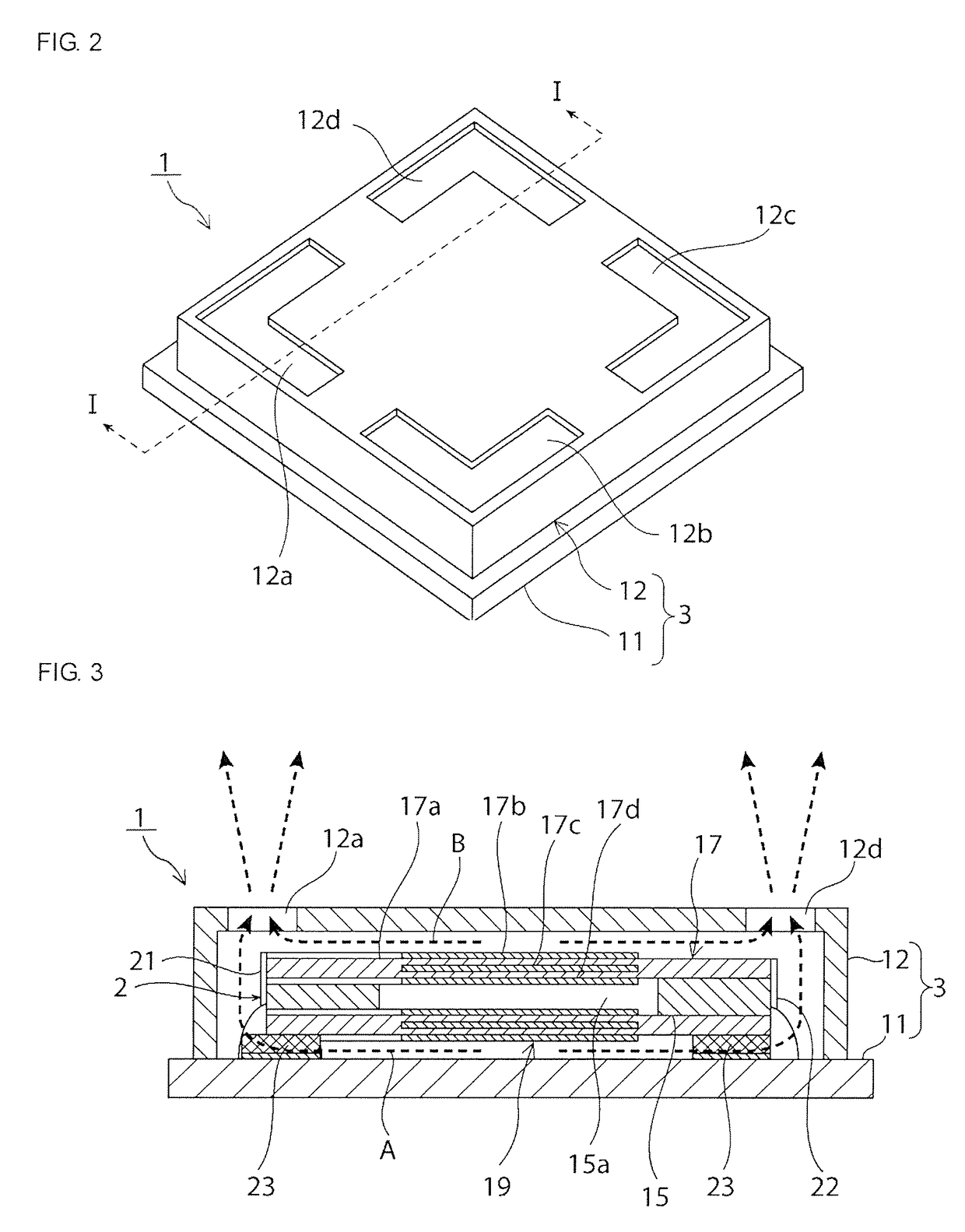
[0028]FIG. 1(a) is an exploded perspective view of an ultrasonic generator 1 according to a first embodiment of the present invention. FIG. 2 is an external perspective view thereof. FIG. 3 is a front sectional view thereof.

[0029]The ultrasonic generator 1 includes an ultrasonic generating element 2 that generates ultrasonic waves, and a case 3. The ultrasonic generating element 2 is accommodated in the case 3.

[0030]The case 3 includes a plate-shaped first case member 11 and a cap-shaped second case member 12. That is, the second case member 12 having an open lower side is secured to the plate-shaped first case member 11. As a result, the case 3 having an internal accommodation space is formed. The ultrasonic generating element 2 is accommodated in the accommodation space.

[0031]As shown in the perspective view of FIG. 2, a plurali...


PUM


Abstract

An ultrasonic generator that is capable of increasing output sound pressure is provided.An ultrasonic generating element is accommodated in an accommodation space that is formed by a first case member and a second case member. The ultrasonic generating element is secured to the first case member via a plurality of first supporting members. The first supporting members are provided so that, in a first acoustic path that includes a space formed between a bottom surface of the ultrasonic generating element and a top surface of the first case member and that extends to sound-wave emission holes, a transverse section of the acoustic path has a portion that becomes smaller than another portion thereof.

Description

CROSS-REFERENCE TO RELATED APPLICATIONS[0001]The present application is a continuation of PCT / JP2013 / 053407 filed Feb. 13, 2013, which claims priority to Japanese Patent Application No. 2012-037503, filed Feb. 23, 2012, the entire contents of each of which are incorporated herein by reference.FIELD OF THE INVENTION[0002]The present invention relates to an ultrasonic generator including an ultrasonic generating element using a piezoelectric vibrator. More specifically, the present invention relates to an ultrasonic generator in which an ultrasonic generating element is accommodated in a case and an acoustic path extending from the ultrasonic generating element to a sound-wave emission hole, provided in the case, is formed.BACKGROUND OF THE INVENTION[0003]Nowadays, as an accurate distance measurement method, a distance measurement method using ultrasonic waves is being used. In this method, ultrasonic waves are emitted from an ultrasonic generator and are caused to strike a measuremen...

Claims


Application Information

Patent Timeline
Patent Type & Authority Patents(United States)
IPC IPC(8): H01L41/09B06B1/06H04R1/02G10K9/125H02N2/18G10K9/22
CPCH02N2/18B06B1/06G10K9/22G10K9/125B06B1/0603
Inventor YAMAMOTO, HIRONARIMITANI, AKIHIRO
Owner MURATA MFG CO LTD
Why Eureka
Try Eureka