Mems ultrasonic transducer with high emission performance

An ultrasonic transducer, ultrasonic technology, applied in the direction of fluid using vibration, etc., can solve the problems of unable to meet the bandwidth requirements, difficult to achieve bandwidth, insufficient emission sound pressure, etc., to optimize the size of the deep groove and increase the emission sensitivity , Improve the effect of output sound pressure

Active Publication Date: 2022-03-15
武汉敏声新技术有限公司
View PDF13 Cites 0 Cited by
  • Summary
  • Abstract
  • Description
  • Claims
  • Application Information

AI Technical Summary

Problems solved by technology

However, due to the characteristics of pMUT, compared with cMUT, it is difficult to achieve a bandwidth of more than 100%, and the bandwidth is relatively small, which cannot meet the bandwidth requirements of some ranging or imaging applications.
In addition, the emission sound pressure of a single pMUT is insufficient, and its emission performance needs to be improved

Method used


Image

  • Mems ultrasonic transducer with high emission performance
  • Mems ultrasonic transducer with high emission performance
  • Mems ultrasonic transducer with high emission performance

Examples


Embodiment Construction

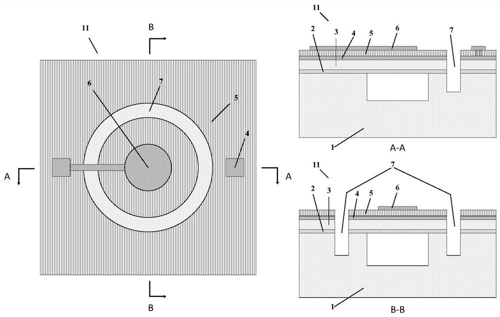
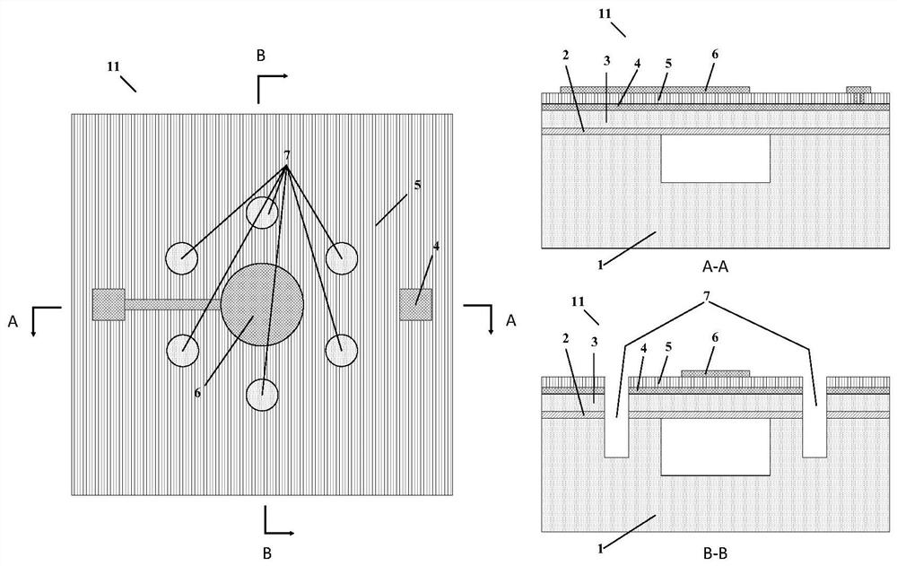
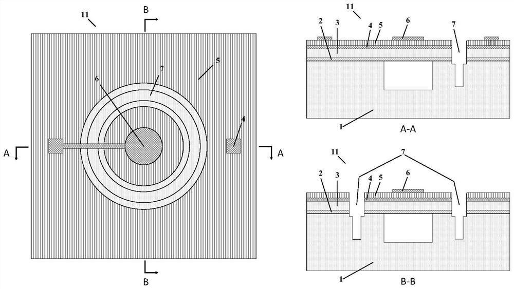
[0026] The MEMS ultrasonic transducer includes sequentially stacked substrates 1, SiO 2 layer 2, passive layer 3, lower electrode 4, piezoelectric layer 5 and upper electrode 6. figure 1 An ultrasonic transducer 11 is shown having a penetrating piezoelectric layer 5, a bottom electrode 4, a passive layer 3 and SiO 2 Deep groove 7 of layer 2 , deep groove 7 extends over a length in substrate 1 . When the ultrasonic wave emitted by the ultrasonic transducer 11 reaches the deep groove 7, it will cause the medium in the deep groove 7 to vibrate, and radiate sound waves outward. The sound field on the surface of 11 interacts, and the distribution of the additional sound field can be adjusted by adjusting the size of the deep groove 7, such as length, width, and the distance from the central axis of the ultrasonic transducer 11, so as to realize the loud pressure output of the ultrasonic transducer 11 Or widen the bandwidth. Specifically, the sound pressure of the ultrasonic tran...


PUM


Abstract

The invention relates to a MEMS ultrasonic transducer with high emission performance. The emission sound pressure or bandwidth is improved by setting deep grooves on the ultrasonic transducer, wherein the distribution of deep grooves includes the following three types: one or more deep grooves run through the ultrasonic transducer Energy device piezoelectric layer, bottom electrode, passive layer, SiO 2 layer, and extends into the substrate; the ultrasonic transducer is bonded with a layer of silicon layer on the upper surface away from the substrate, and the part facing the diaphragm of the ultrasonic transducer is provided with an opening through the silicon layer as a waveguide, one or A plurality of deep grooves are distributed around the waveguide; one or more deep grooves are distributed around the back cavity etched on the substrate of the flip-chip ultrasonic transducer. When the sound wave emitted by the ultrasonic transducer passes through the deep groove, it will cause the medium in the deep groove to vibrate. This vibration will generate an additional sound field on the diaphragm of the ultrasonic transducer. By adjusting the size of the deep groove, the additional sound field can be adjusted, thereby Adjust the emission performance of the ultrasonic transducer such as emission pressure, bandwidth, and directivity.

Description

technical field [0001] The invention relates to a MEMS ultrasonic transducer, in particular to a MEMS ultrasonic transducer with high emission sound pressure or large bandwidth. Background technique [0002] Ultrasonic transducers are transducer devices that can convert electrical energy into acoustic energy and convert acoustic energy into electrical energy, so ultrasonic transducers can be used for both transmitting and receiving ultrasonic waves. At present, the most widely used ultrasonic transducers are based on bulk piezoelectric transducers. Bulk piezoelectric transducers mainly use the vibration of piezoelectric ceramics. Since the resonance frequency is only related to the thickness of piezoelectric ceramics, it is difficult to Fabricate ultrasonic transducers with different resonant frequencies. In addition, the thickness of piezoelectric ceramics of this kind of transducer is difficult to control at sub-micron precision, so it is not suitable for high frequency. ...

Claims


Application Information

Patent Timeline
Patent Type & Authority Patents(China)
IPC IPC(8): B06B1/06
CPCB06B1/0644
Inventor 孙成亮朱伟吴志鹏王磊林炳辉胡博豪
Owner 武汉敏声新技术有限公司
Why Eureka
Try Eureka