Method and device for coupling a first sensor to at least one second sensor

a technology of at least one sensor and a second sensor, which is applied in the field of coupling a first sensor to at least one second sensor, can solve the problems of reducing the performance capability of the bus system, recognizing errors, and limited number of sensors in one branch of the bus, so as to achieve rapid and efficient

Active Publication Date: 2017-05-30
ROBERT BOSCH GMBH
View PDF19 Cites 0 Cited by
  • Summary
  • Abstract
  • Description
  • Claims
  • Application Information

AI Technical Summary

Benefits of technology

[0014]The third signal may be output time-delayed with respect to the second signal. Communication reliability may thus prevail on the data bus. The measured value of the second sensor cannot be corrupted by the measured value of the first sensor.
[0020]Furthermore, the present invention provides a device which is designed to carry out or implement the steps of the method according to the present invention in corresponding units. The object on which the present invention is based may also be achieved rapidly and efficiently by this embodiment variant of the present invention in the form of a device.

Problems solved by technology

Independently of whether individual queries of items of information or a continuous provision of the information is / are carried out via a data bus, the bus is strained in both cases by a large amount of data communication, which may reduce a performance capability of the bus system.
For example, a number of sensors in one branch of the bus may be limited by a transportable data quantity via the branch of the data bus.
If comparable results are expected for the measured values, an error may be recognized in the event of an unexpected deviation of the results from one another.

Method used


Image

  • Method and device for coupling a first sensor to at least one second sensor
  • Method and device for coupling a first sensor to at least one second sensor
  • Method and device for coupling a first sensor to at least one second sensor

Examples


Embodiment Construction

[0028]In the following description of preferred exemplary embodiments of the present invention, identical or similar reference numerals are used for the elements which are shown in the various figures and act similarly, a repeated description of these elements being omitted.

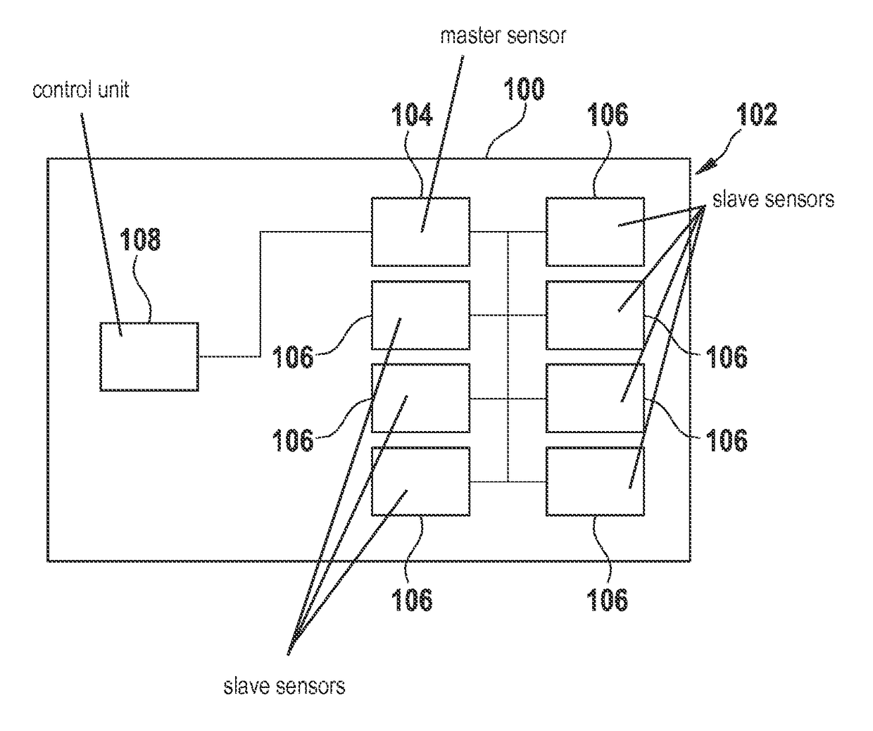
[0029]FIG. 1 shows a vehicle 100 having a sensor array 102 including eight sensors 104, 106 according to one exemplary embodiment of the present invention. An item of information of sensor array 102 is used by a control unit 108. Sensors 104, 106 of sensor array 102 are connected to one another using a first data bus. One of sensors 104, 106 is connected as a master sensor 104 via a second data bus to control unit 108. The other sensors 106 are slave sensors 106. Master sensor 104 is designed for the purpose of transmitting a first signal via the first data bus to slave sensors 106. Slave sensors 106 are designed in this exemplary embodiment to provide a second signal in each case via the first data bus, after th...


PUM


Abstract

A method for coupling a first sensor to at least one second sensor is provided, the method including a step of transmitting a first signal from the first sensor to the at least one second sensor. Furthermore, the method includes a step of providing a second signal by way of the second sensor. The second signal is provided in response to the first signal, the second signal representing a measured value of the second sensor. Furthermore, the method includes a step of outputting a third signal for a control unit by way of the first sensor. The outputting of the third signal is carried out in response to the second signal, the third signal representing at least one measured value of the first sensor.

Description

FIELD[0001]The present invention relates to a method for coupling a first sensor to at least one second sensor, a corresponding device, and a corresponding computer program product.BACKGROUND INFORMATION[0002]To query conventional sensors via a bus system, the sensors are individually queried by a control unit. The sensors may also provide items of information in an unregulated way via the bus, which the control unit may input as needed.[0003]For example, German Patent Application No. DE 10 2009 029 217 A1 describes an inertial sensor having a field-effect transistor, which includes a gate electrode, a source electrode, a drain electrode, and a channel area situated between the source electrode and the drain electrode. The gate electrode is stationary and the channel area is designed to be movable.SUMMARY[0004]Against this background, the present invention provides a method for coupling a first sensor to at least one second sensor, furthermore, a device which uses this method, and f...

Claims


Application Information

Patent Timeline
Patent Type & Authority Patents(United States)
IPC IPC(8): G06F3/00G06F13/00G06F13/40G06F13/38G06F13/12H04L29/08H04L12/403G06F13/28
CPCG06F13/4063H04L12/403H04L67/125G01D21/00
Inventor KOSSIRA, MARTINSEIDEL, JANARUFF, ALEX
Owner ROBERT BOSCH GMBH
Why Eureka
Try Eureka