
Interchangeable resistance tube assembly

a resistance tube and assembly technology, applied in the field of resistance tubes, can solve the problems of difficult exchange of tubing, secure and safe holding,

Active Publication Date: 2017-06-13
PRISM FITNESS
View PDF19 Cites 4 Cited by
  • Summary
  • Abstract
  • Description
  • Claims
  • Application Information

AI Technical Summary

Benefits of technology

[0010]Additionally, a user may then increase and decrease the resistance on the resistance tube handle for a selected exercise regimen by interchanging the resistance tube with one of another resistance level, and / or by adding or subtracting resistance tubes where there is a multiple pocket handle base.
[0011]It is an object of the present invention to provide a handle for securely gripping a resistance tube end which is readily released to permit changing of one resistance tube for another.

Problems solved by technology

However, these systems may not securely and safely hold resistance tubing in place, and may be time consuming and difficult to exchange tubing.

Method used


Image

  • Interchangeable resistance tube assembly
  • Interchangeable resistance tube assembly
  • Interchangeable resistance tube assembly

Examples


Embodiment Construction

[0020]In the following detailed description, reference is made to the accompanying drawings, which form a part hereof. In the drawings, similar symbols typically identify similar components, unless context dictates otherwise. The illustrative embodiments described in the detailed description, drawings, and claims are not meant to be limiting. Other embodiments may be used, and other changes may be made, without departing from the spirit or scope of the subject matter presented here. It will be readily understood that the aspects of the present disclosure, as generally described herein, and illustrated in the Figures, may be arranged, substituted, combined, and designed in a wide variety of different configurations, all of which are explicitly contemplated and make part of this disclosure.

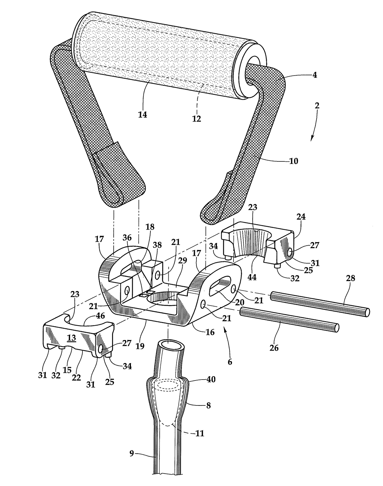
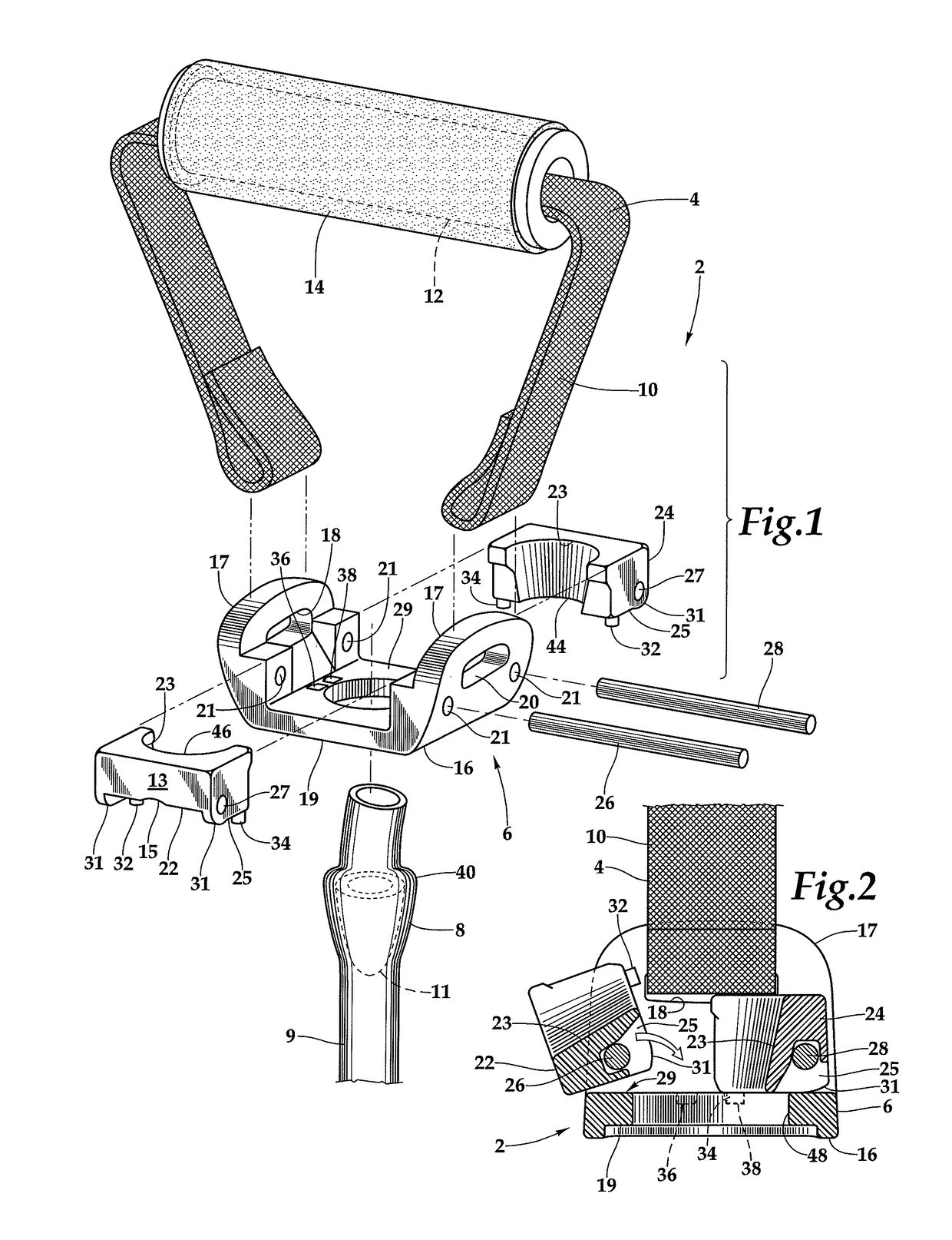
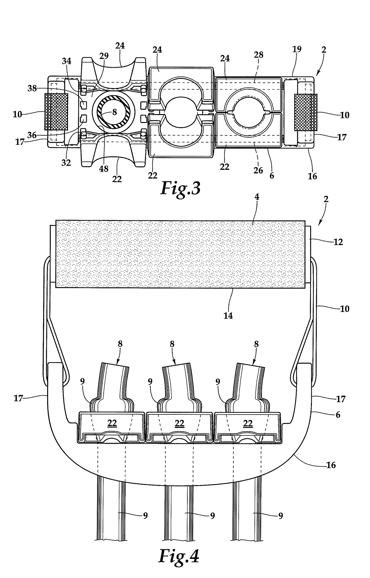
[0021]Referring to FIGS. 1 and 2, an apparatus 2 is shown with a handle assembly 4 and tube assembly 6, which engages a resistance tube 8 in the locked position. The handle assembly 4 includes a gri...


PUM


Abstract

A handle assembly base has a central tube opening for receiving an elastic resistance tube with an expanded end diameter. A first block and a second block are pivotably mounted to the base on opposite sides of the central tube opening. When pivoted towards each other, the blocks define a reduced area opening through which the expanded end diameter of the resistance tube cannot pass, thereby retaining the resistance tube to the base. The base has two opposed ears which extend upwardly of the central tube opening. A flexible strap is secured to the ears, and extends through a cylindrical tube to which a flexible handle cushion is mounted to provide a grip for the user to engage the handle.

Description

CROSS REFERENCES TO RELATED APPLICATIONS[0001]The application claims the benefit of priority of U.S. provisional patent App. No. 62 / 100,469, filed Jan. 6, 2015, the disclosure of which is incorporated by reference herein.STATEMENT AS TO RIGHTS TO INVENTIONS MADE UNDER FEDERALLY SPONSORED RESEARCH AND DEVELOPMENT[0002]Not applicable.BACKGROUND OF THE INVENTION[0003]The present disclosure generally pertains to exercise and medical rehabilitation apparatus, and more particularly, to resistance tubes used for fitness, exercise, and medical rehabilitation. Some examples of resistance tubes according to the present disclosure may be used for fitness training to tone muscle and increase strength, while others may be used for physical rehabilitation following injury or medical procedures.[0004]Resistance bands or tubing comes in multiple elasticities to provide a selection of varying weights and sizes. Oftentimes, a handle is permanently affixed on each end of the tubing, and each weight an...

Claims


Application Information

Patent Timeline
Patent Type & Authority Patents(United States)
IPC IPC(8): A63B21/00A63B21/02A63B21/055A63B23/12A63B71/00A63B21/002A63B71/06
CPCA63B21/00061A63B21/00043A63B21/00065A63B21/026A63B21/0552A63B21/0557A63B21/4035A63B23/12A63B21/0023A63B23/1209A63B23/1245A63B71/0054A63B2071/0625A63B2071/0655A63B2208/0204
Inventor CHEN, WENG KINSOTIS, WILLIAM J.
Owner PRISM FITNESS
Learn More