Object display device

a technology of object display and display device, which is applied in the field of object display device, can solve the problems of increasing the processing load of the calculation device, increasing the calculation amount, increasing the animation production time and cost,

a technology of object display and display device, which is applied in the field of object display device, can solve the problems of increasing the processing load of the calculation device, increasing the calculation amount, increasing the animation production time and cost,

US9675887B2Active Publication Date: 2017-06-13SQUARE ENIX HLDG CO LTD

Image

  • Object display device
  • Object display device
  • Object display device

Examples


Embodiment Construction

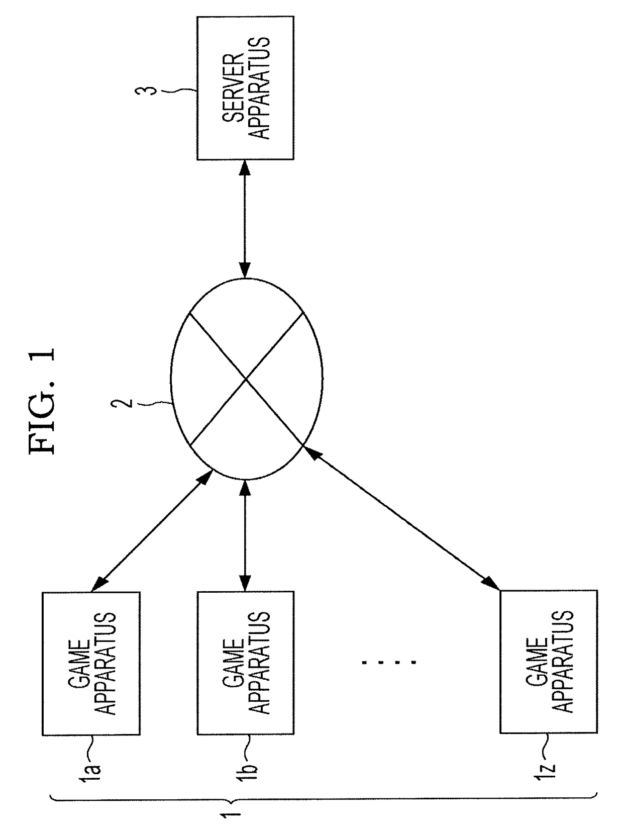
[0025]Hereinafter, embodiments of the present invention will be described with reference to the accompanying drawings. In the present embodiment, the case of applying the present invention to an MMORPG is mainly described as an example. FIG. 1 is a block diagram illustrating a configuration of a game system according to an embodiment of the present invention. As illustrated in FIG. 1, the game system includes a plurality of game apparatuses 1 (game apparatuses 1a, 1b . . . 1z) operated by a plurality of players A, B . . . Z), a server apparatus 3, and a communication network 2. The game apparatuses 1 are connected to the server apparatus 3 through the communication network 2. In addition, the game apparatuses 1 need not be always connected to the server apparatus 3, and may be connected on an as-needed basis. The game apparatuses 1a to 1z are connected to the server apparatus 3, and the players may play the same game by operating a player character allocated to each of the game appa...


PUM


Abstract

A polygon of a skirt is beforehand set in association with a skirt bone such that the polygon is at an angle of β to the skirt bone. The movement of the skirt bone is controlled according to the movement of a thigh bone. When a character walks or runs, if the thigh bone is inclined at an angle of α, each of the skirt bone and the polygon is inclined at an angle of α in a direction perpendicular to the ground surface. Therefore, since a polygon and the polygon do not interest each other, it is possible to prevent a thigh portion of the character from penetrating the skirt unnaturally.

Description

CROSS REFERENCE TO RELATED APPLICATIONS[0001]The present disclosure relates to subject matter contained in Japanese Patent Application No. 2012-171533, filed on Aug. 1, 2012, and Japanese Patent Application No. 2013-145236, filed on Jul. 11, 2013, the disclosure of which is expressly incorporated herein by reference in its entirety.TECHNICAL FIELD[0002]The present invention relates to an object display device that can realistically display an activation of an object such as a character accessory or a character hair, which is controlled through a realistic activation by performing physics calculation processing, by a small amount of calculation without an uncomfortable feeling without performing physics calculation processing.BACKGROUND ART[0003]In the past, in order to represent a more realistic game screen, the movement of a skirt and mantle of a character or a hair of the character is controlled by performing physics calculation considering the influence of gravity and wind. Howev...

Claims


Application Information

Patent Timeline
13 Jun 2017
Publication
US9675887B2
IPC
A63F13/57; G06T13/20
CPC
A63F13/57; G06T13/20; A63F2300/6607
Inventors
SAOTOME, HIROAKI