

Switching power supply apparatus and semiconductor device
a technology of switching power supply and semiconductor device, which is applied in the direction of power conversion system, dc-dc conversion, instruments, etc., can solve the problems of affecting the size reduction and cost reduction affecting the efficiency and the dominant energy loss of the switching power supply apparatus is a switching loss, etc., to achieve simple configuration, reduce the effect of the peak value and the limitation of the operating frequency rang
- Summary
- Abstract
- Description
- Claims
- Application Information
AI Technical Summary
Benefits of technology
Problems solved by technology
Method used
Image

Examples
embodiment 1
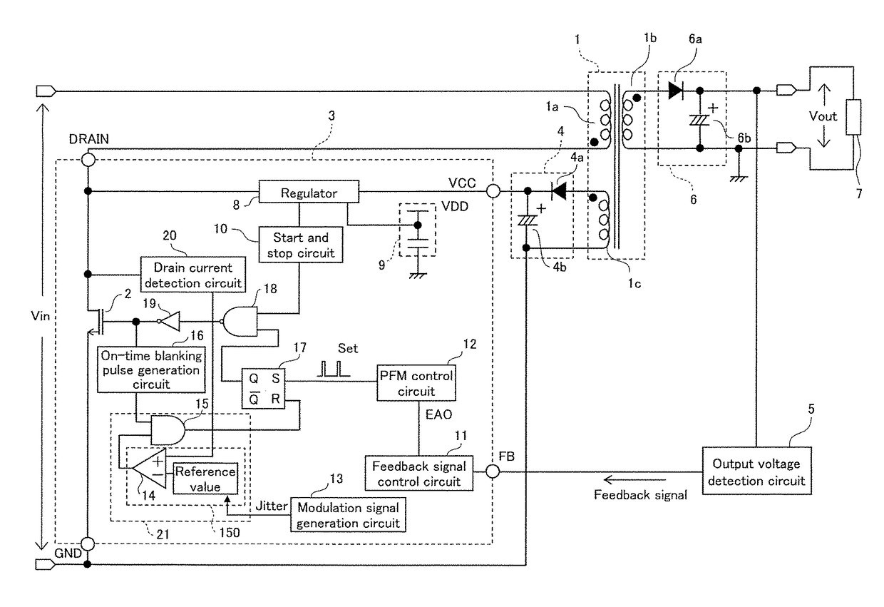
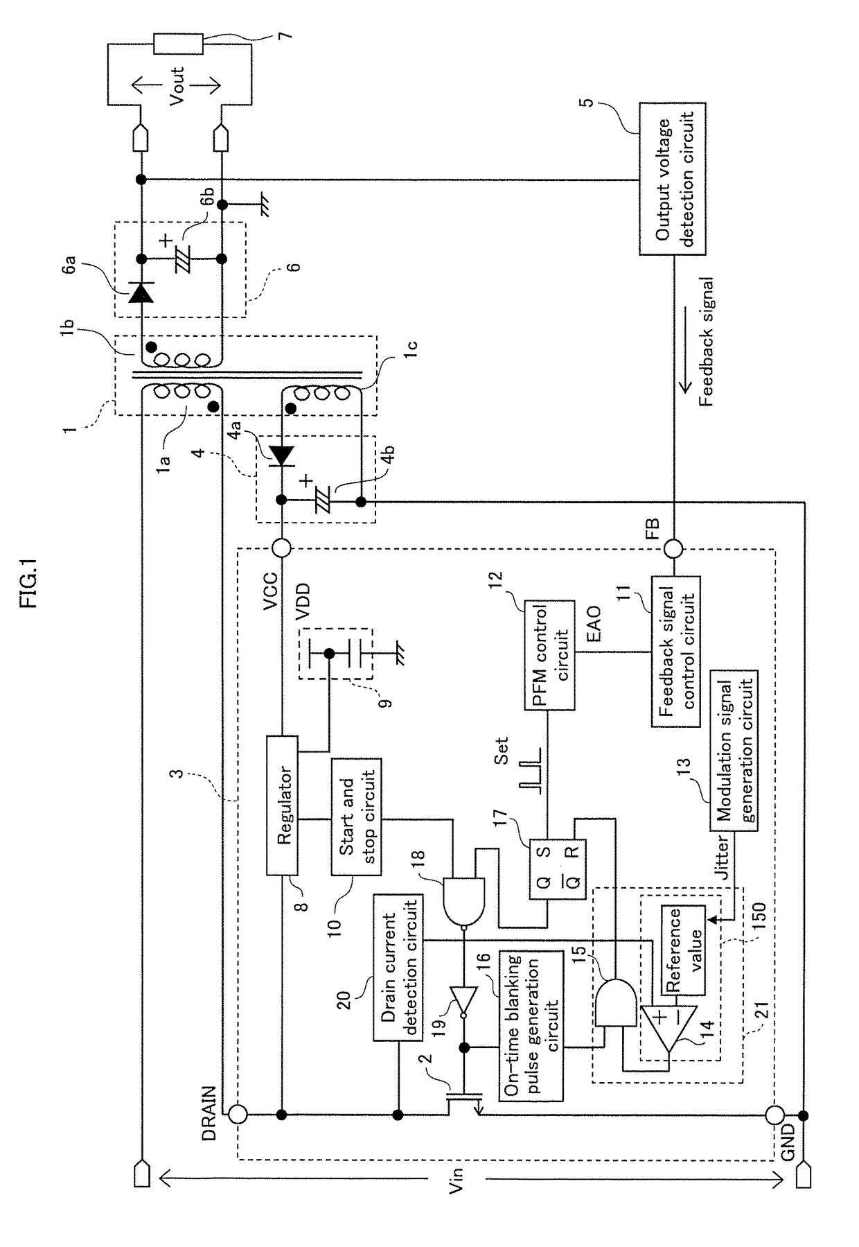
[0046]FIG. 1 is a circuit diagram showing a configuration example of a switching power supply apparatus that includes a semiconductor device for controlling a switching power relating to
[0047]As shown in FIG. 1, a transformer 1 includes a primary coil 1a, a secondary coil 1b, and an auxiliary coil 1c. The primary coil 1a and the secondary coil 1b are opposite in polarity to each other. This switching power supply apparatus is of a flyback type.
[0048]A switching element 2 constituting part of a control circuit 3 is connected with the primary coil 1a. A switching operation of the switching element 2 is controlled through variation of a voltage to be applied to a control electrode (gate) of the switching element 2.
[0049]The switching element 2 and other part that constitute the control circuit 3 are integrated on the same semiconductor substrate, and constitute a single semiconductor device. The switching element 2 is a power MOSFET or the like.
[0050]Note that the switching element 2 a...
embodiment 2
[0163]The following describes a switching power supply apparatus relating to Embodiment 2 of the present disclosure.
[0164]FIG. 14 is a circuit diagram of the switching power supply apparatus relating to present embodiment.
[0165]The switching power supply apparatus relating to the present embodiment differs in terms of the following point from the switching power supply apparatus relating to Embodiment 1 shown in FIG. 1. In the switching power supply apparatus relating to Embodiment 1, the drain current is detected by the drain current detection circuit 20. When the current reaches the set reference value, the switching element 2 turns off. In the switching power supply apparatus relating to the present embodiment compared with this, an on-time generation circuit 22 is provided for always setting a fixed on-time irrespective of a value of a current flowing through a switching element 2. When turn-on of the switching element 2 is detected, a turn-on signal is input to an on-time gener...
embodiment 3
[0171]The following describes a switching power supply apparatus relating to Embodiment 3 of the present disclosure.
[0172]FIG. 15 is a circuit diagram of the switching power supply apparatus relating to present embodiment.
[0173]The switching power supply apparatus relating to the present embodiment basically has the same circuit configuration as that of the switching power supply apparatus relating to Embodiment 1. The switching power supply apparatus relating to the present embodiment differs from the switching power supply apparatus relating to Embodiment 1 in terms of that a TR terminal is used instead of the FB terminal, an off-timing of a secondary current is detected by the TR terminal, and the on-duty of the secondary current is adjusted in a certain load range such that the load state maintains an output current at a constant value.
[0174]A rectifying and smoothing circuit 4 which is configured by a rectifying diode 4a and a smoothing capacitor 4b is connected with an auxilia...
PUM
 Abstract
Description
Claims
Application Information