Check patentability & draft patents in minutes with Patsnap Eureka AI!

Phase interpolator and clock and data recovery circuit

a phase interpolator and clock technology, applied in the direction of digital transmission, pulse automatic control, electrical apparatus, etc., can solve the problem of difficult to ensure the performance of both, and achieve the effect of wide operation frequency range without reducing the maximum operation speed

Active Publication Date: 2017-02-28
GLOBAL UNICHIP CORPORATION +1
View PDF10 Cites 4 Cited by
  • Summary
  • Abstract
  • Description
  • Claims
  • Application Information

AI Technical Summary

Benefits of technology

The invention provides a phase interpolator and a clock and data recovery circuit that can operate over a wide range of frequencies without slowing down. This is accomplished through a circuit structure that reduces parasitic capacitive effects, resulting in a higher degree of linearity and lower jitter in the phase interpolation signal.

Problems solved by technology

Since the operation frequency range and the operation speed of the receiver are critically affected by circuit characteristics of the phase interpolator, designer may need more time to develop a trade-off between the operation frequency range and the operation speed, whereas it is rather difficult to ensure the performance of both.

Method used


Image

  • Phase interpolator and clock and data recovery circuit
  • Phase interpolator and clock and data recovery circuit
  • Phase interpolator and clock and data recovery circuit

Examples


Embodiment Construction

[0023]In order to make the disclosure more comprehensible, embodiments are described below as examples showing that the disclosure can actually be realized. The embodiments provided herein are only for an illustrative purpose, instead of limiting the scope of the disclosure. Moreover, wherever possible, the same reference numbers are used in the drawings and the description of embodiments to refer to the same or like parts.

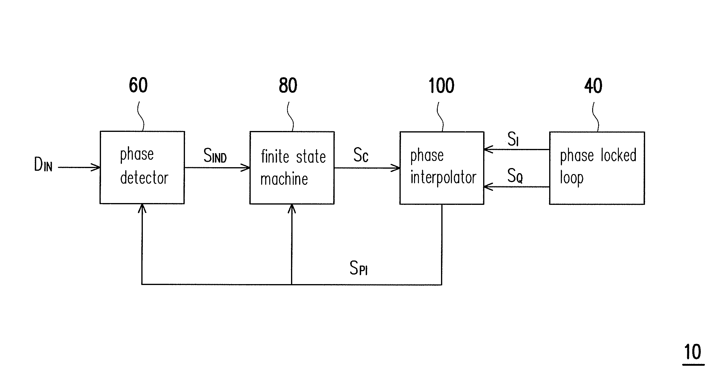
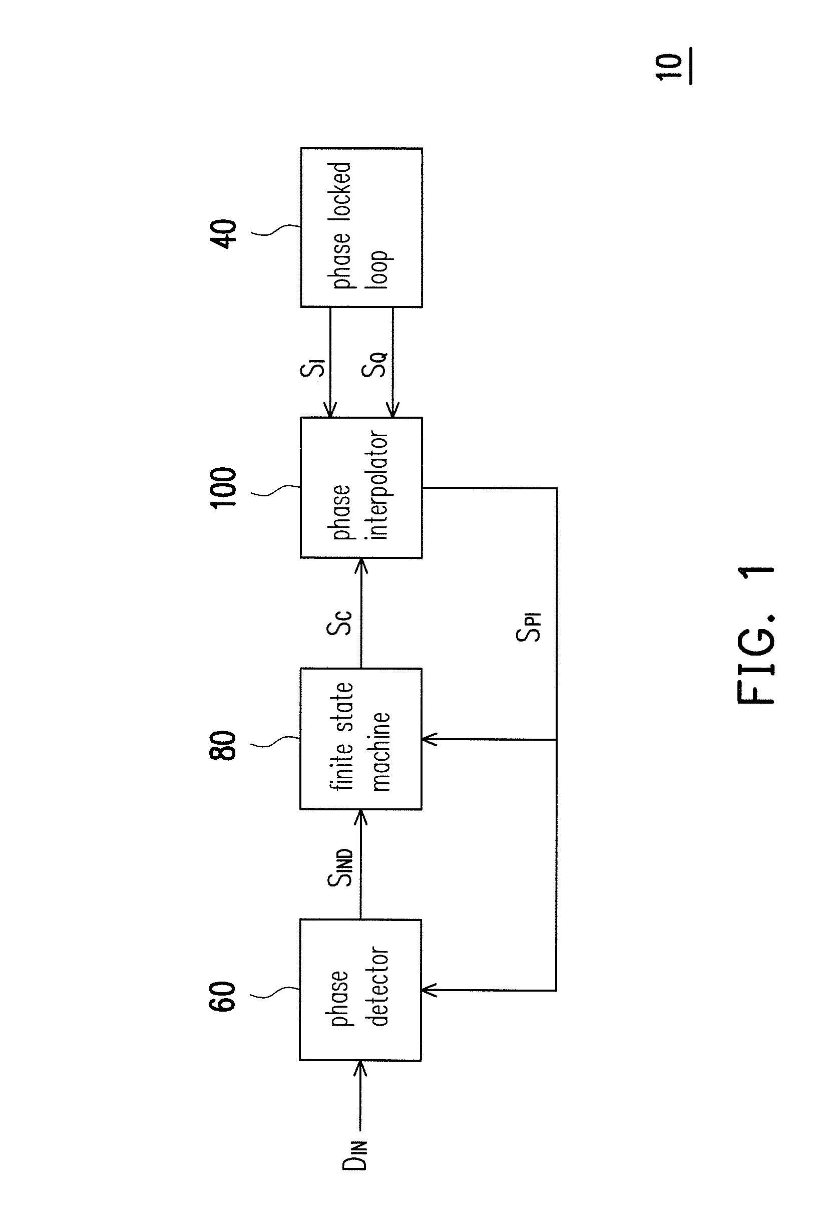
[0024]FIG. 1 is a block diagram of a clock and data recovery circuit (CDR) according to an embodiment of the disclosure. In the present embodiment, the CDR circuit 10 can be disposed in a receiver for recovering clock of the input data received from a transmitter. With reference to FIG. 1, the CDR circuit 10 includes a phase locked loop (PLL) 40, a phase detector 60, a finite state machine (FSM) 80, and a phase interpolator 100. The PLL 40 is coupled to the phase interpolator 100 and generates a first clock signal SI and a second clock signal SQ, the first clock s...


PUM


Abstract

A phase interpolator including a phase interpolation circuit, a plurality of low pass filtering channels, and a multiplexing circuit is provided. The phase interpolation circuit receives a first clock signal and a second clock signal and accordingly performs an interpolation operation to generate an output clock signal. The low pass filtering channels respectively have an output terminal and an input terminal that is coupled to the phase interpolation circuit to receive the output clock signal. Each of the low pass filtering channels includes a switch and a capacitor which are coupled to a common node as the output terminal. The multiplexing circuit has a plurality of input terminals respectively coupled to the output terminals of the low pass filtering channels. The multiplexing circuit selects an input signal received from one of the low pass filtering channels as a phase interpolation signal according to a selecting signal.

Description

BACKGROUND[0001]Field of Invention[0002]The invention generally relates to a phase interpolator; more particularly, the invention relates to a phase interpolator and a clock and data recovery circuit using the same, so as to obtain a wide operation frequency range without reducing the maximum operation speed due to parasitic capacitive effects.[0003]Description of Prior Art[0004]Clock and data recovery (CDR) circuits are generally used to sample an input data signal, extract the clock from the input data signal, and retime the sampled data in the receiver. In a conventional CDR circuit, a phase interpolator for adjusting the phase of the sampling clock is frequently employed.[0005]Since the operation frequency range and the operation speed of the receiver are critically affected by circuit characteristics of the phase interpolator, designer may need more time to develop a trade-off between the operation frequency range and the operation speed, whereas it is rather difficult to ensur...

Claims


Application Information

Patent Timeline
Patent Type & Authority Patents(United States)
IPC IPC(8): H04L7/00H04L7/033
CPCH04L7/0025H04L7/0331H03L7/0998
Inventor CHIEN, TING-HSULEE, YI-LINWANG, JU-CHIEH
Owner GLOBAL UNICHIP CORPORATION
Features
  • R&D
  • Intellectual Property
  • Life Sciences
  • Materials
  • Tech Scout
  • Unparalleled Data Quality
  • Higher Quality Content
  • 60% Fewer Hallucinations
Learn More