
Phase-locked loop and method for calibrating voltage-controlled oscillator therein

a voltage-controlled oscillator and phase-locked loop technology, applied in the direction of electrical apparatus, pulse automatic control, etc., can solve the problems of change of loop characteristics, increase of vco gain, and serious affecting of operating stability and noise characteristics of vco, so as to achieve the best performance, wide operating frequency range, and superior noise performance

Active Publication Date: 2020-12-24
GOWIN SEMICON CORP LTD
View PDF0 Cites 6 Cited by
  • Summary
  • Abstract
  • Description
  • Claims
  • Application Information

AI Technical Summary

Benefits of technology

The present invention provides a phase-locked loop and a method for calibrating the VCO (voltage-controlled oscillator) therein. The calibration circuit can acquire the frequency of the output signal from the VCO and calibrate it according to the desired frequency. The amplitude and gain of the output signal of the VCO are kept constant according to the amplitude control parameters and gain control parameters. The phase-locked loop provided by the present invention has a very wide operating frequency range and superior noise performance, can meet the demands on frequency of multiple protocols and can adaptively look up and stabilize the suitable frequency, so that the circuit has the best performance. Additionally, the issue that the amplitude of the output signal of the VCO is not constant when the phase-locked loop operates in a large frequency range is solved by the present invention.

Problems solved by technology

And the voltage signal will increase, which will lead to the voltage limit of the relevant module and seriously affect operating stability and noise characteristics of the VCO.
Another disadvantage of the VCO based on LC tank is that with the increase of frequency, the VCO gain will increase, and the change of VCO gain will lead to the change of loop characteristics, which will affect the performance of the phase-locked loop.

Method used


Image

  • Phase-locked loop and method for calibrating voltage-controlled oscillator therein
  • Phase-locked loop and method for calibrating voltage-controlled oscillator therein
  • Phase-locked loop and method for calibrating voltage-controlled oscillator therein

Examples


Embodiment Construction

[0020]In order to make the objects, technical schema and advantages of the present invention clearer, the following detailed description is provided for further understanding of the present invention with the accompanying drawings and embodiments. It should be understood that the specific embodiments described herein are merely intended to explain the invention and are not intended to limit the invention.

[0021]The following embodiments will illustrate the technical schema of the present invention.

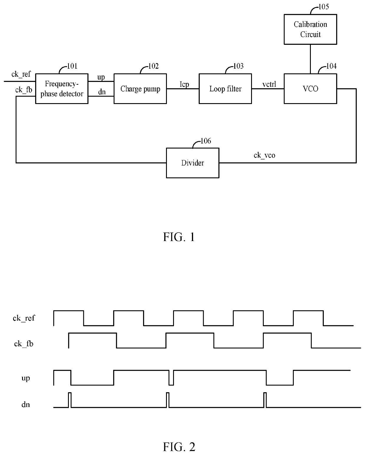
[0022]The exemplary embodiment of the present invention provides a phase-locked loop, as shown in FIG. 1, comprising: a frequency-phase detector 101 used to generate pulse modulation signals of different widths according to a phase difference between two input square wave signals; a charge pump 102 used to output current pulses according to the pulse modulation signal inputted; a loop filter 103 used to perform low-pass filtering on the current pulses and output a voltage control signal; a ...


PUM


Abstract

A phase-locked loop (PLL) and a method for calibrating a VCO therein are provided. The PLL comprises a frequency-phase detector, a charge pump, a loop filter, a VCO, a divider and a calibration circuit. The calibration circuit is used to acquire a frequency of an output signal of the VCO, to calibrate the frequency of the output signal according to an expected frequency, and to acquire frequency control parameters of the VCO at the current signal frequency. The amplitude and gain of the output signal are kept constant according to the amplitude control parameters and gain control parameters. The PLL can meet the demands on frequencies of multiple protocols and can adaptively look up and stabilize the suitable frequency. It solves the issue that the amplitude of the output signal of the VCO is not constant when the PLL operates in a large frequency range.

Description

CROSS-REFERENCE TO RELATED APPLICATIONS[0001]This application claims priority to Chinese Patent Application No. 201910546728.7 with a filing date of Jun. 24, 2019. The content of the aforementioned application, including any intervening amendments thereto, is incorporated herein by reference.TECHNICAL FIELD[0002]The exemplary embodiment of present invention relates to the field of phase-locked loop circuit technology, and in particular, to a phase-locked loop and a method for calibrating a voltage-controlled oscillator (VCO) therein.BACKGROUND OF THE PRESENT INVENTION[0003]The phase-locked loop is an indispensable part of the high-speed communication system. The phase-locked loop provides a suitable clock frequency for the high-speed communication system as a frequency synthesizer. The phase-locked loop of VCO based on LC tank has excellent phase noise characteristics. It is widely used in the high-speed communication system. The LC tank in VCO has high quality, so its operating fre...

Claims


Application Information

Patent Timeline
Patent Type & Authority Applications(United States)
IPC IPC(8): H03L7/089H03L7/093H03L7/18
CPCH03L7/0895H03L7/18H03L7/093H03L7/099H03L7/087H03L2207/06
Inventor WU, QIMINGLIN, XIAOZHIZHOU, QIANGWANG, YUNFENG
Owner GOWIN SEMICON CORP LTD
Learn More