
Acoustic waveguide

A technology of acoustic waveguide and acoustic waveguide, which is applied in the field of loudspeaker line array high-frequency radiation devices, can solve the problems of chaotic sound field distribution, discontinuous acoustic impedance, performance degradation, etc., and achieve the effect of improving performance and widening the working frequency range

Active Publication Date: 2017-02-22
NANJING UNIV
View PDF8 Cites 5 Cited by
  • Summary
  • Abstract
  • Description
  • Claims
  • Application Information

AI Technical Summary

Problems solved by technology

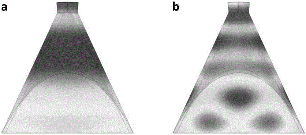
For example, the DOSC acoustic waveguide has a geometric discontinuity at the joint part of its structure from the cone surface to the plane, resulting in discontinuity of the acoustic impedance here. Therefore, when the frequency is high, the sound field distribution is more chaotic, and its performance is greatly reduced.
like figure 2 As shown, the performance of the DOSC acoustic waveguide has dropped significantly at 5kHz

Method used


Image

  • Acoustic waveguide
  • Acoustic waveguide
  • Acoustic waveguide

Examples


Embodiment Construction

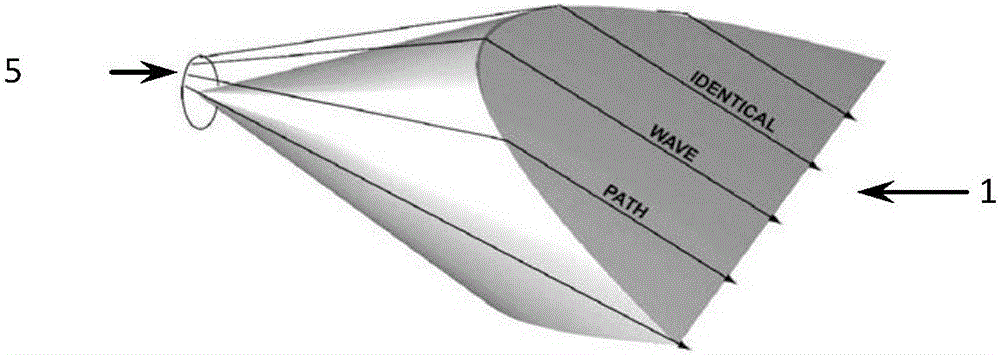
[0028] The present invention proposes the key points of the design of the internal waveguide of the acoustic waveguide, uses a layered structure as required, and adopts the "equal acoustic path method" to design the overall waveguide distribution, which solves the problem of the unsatisfactory structure of the traditional acoustic waveguide including the DOSC acoustic waveguide. The resulting decrease in acoustic performance broadens the operating frequency range of the acoustic waveguide.

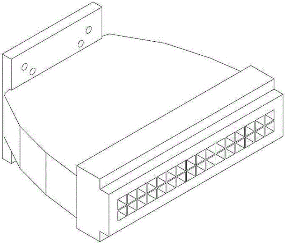
[0029] The present invention is a design structure of a loudspeaker line array acoustic waveguide, which will be described below in combination with specific design schematic diagrams. In the acoustic waveguide, the throat of the waveguide is installed on the driver unit of the speaker, and the waveguide mouth is generally narrow and rectangular; the structure of the waveguide from the throat of the waveguide to the waveguide mouth is as follows: Figure 8 As shown, several waveguides are ...


PUM

PropertyMeasurementUnit
Lengthaaaaaaaaaa

Abstract

Provided is an acoustic waveguide. An internal acoustic waveguide tube of the acoustic waveguide includes a binary-tree or ternary-tree multilevel bifurcate waveguide tube. The waveguide tube of each bifurcate structure includes a straight tube and a corner guide tube. The cross section of the acoustic waveguide tube is rectangular, circular, oval or polygonal. The cross-section area of the waveguide tube of each bifurcate structure must be small enough, and the largest-dimension size of the cross section is generally not more than 2cm. The straight tube of the waveguide tube of each bifurcate structure must be long enough, and is generally not shorter than 3cm. For an acoustic waveguide with a wide outlet, the waveguide tube of each bifurcate structure is of a layered structure at the outlet, the number of layers depends on the width of the outlet and the shape of the cross section of the waveguide tube, and the width of each layer is controlled within 2cm.

Description

technical field [0001] The invention relates to an acoustic device, especially a device for high-frequency radiation of a loudspeaker line array. Background technique [0002] The main optimization goal of high-frequency radiation in loudspeaker line arrays is to improve the approximation of the array to the ideal linear line sound source to achieve cylindrical wave radiation, so as to radiate sound energy as far as possible, that is, to improve the "long throw" of the array performance. For this reason, the loudspeaker drivers in the array are usually equipped with acoustic waveguides, which convert the radiation characteristics of the loudspeaker drivers similar to a point sound source to that of a short straight line sound source. By combining these loudspeaker driving units equipped with acoustic waveguides into an array, the radiation characteristic of the array can be approximated as a linear sound source. However, in reality, limited by the installation process and ...

Claims


Application Information

Patent Timeline
IPC IPC(8): H04R9/06H04R9/02
CPCH04R9/02H04R9/06H04R2400/11
Inventor 沈勇冯雪磊薛政邓文翰
Owner NANJING UNIV
Learn More