

No-touch busway plug in units
a busway and plug-in technology, applied in the direction of three-pole connection, coupling device connection, electrical apparatus, etc., can solve the problem of exposed conductors and achieve the effect of not being exposed in the plug-in units
- Summary
- Abstract
- Description
- Claims
- Application Information
AI Technical Summary
Benefits of technology
Problems solved by technology
Method used
Image

Examples
Embodiment Construction
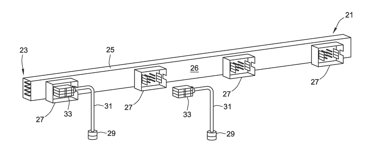
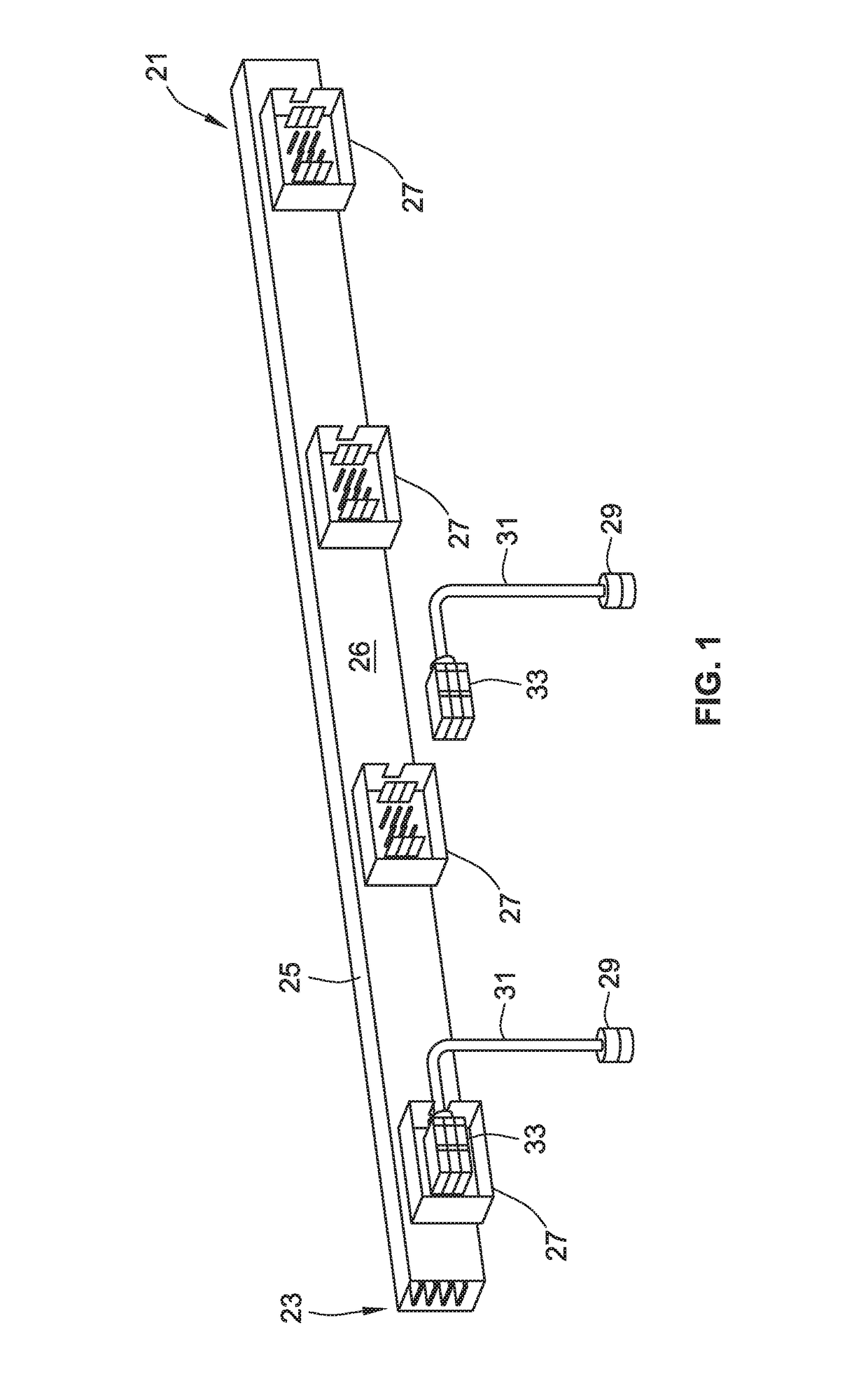
[0005]The embodiments disclosed herein are directed to methods and systems, often known in the art as “finger safe” provisions for reducing or eliminating the possibility of exposure to live parts in a busway, and particularly at the plug in units of the busway, and safely installing and removing a circuit breaker or other branch electrical devices from the conductors within the plug in unit. While the illustrated embodiments are explained with circuit breakers in mind as the branch control device, the present invention is not necessarily limited to a circuit breaker control environment.
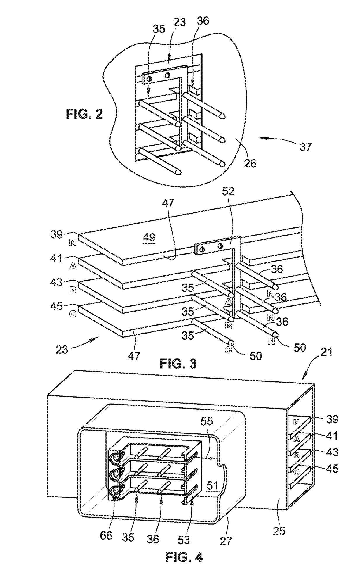
[0006]The disclosed embodiments provide a shutter assembly for the plug in unit that automatically closes off access to pin shaped conductors extending from each bus of the main busway section into the plug in unit until a circuit breaker is inserted in the plug in unit. A shutter assembly is attached in the circuit breaker mounting compartments, sometimes referred to herein as “wells,” of the plug i...
PUM
 Abstract
Description
Claims
Application Information