Transcatheter prosthetic heart valve and delivery system

a transcatheter prosthetic and delivery system technology, applied in the field of cardiovascular treatment, can solve the problems of unacceptably high, difficult and problematic development of a device for percutaneous replacement of the mitral valve, and achieve the effect of safe removal

Active Publication Date: 2017-11-23
EDWARDS LIFESCIENCES CORP
View PDF1 Cites 43 Cited by
  • Summary
  • Abstract
  • Description
  • Claims
  • Application Information

AI Technical Summary

Benefits of technology

[0007]The endoprosthesis is contained in a sheathed capsule and is inserted into the body and advanced to the intended location with a delivery system for percutaneously deploying a prosthetic heart valve. This system apart from the sheathed capsule includes an inner shaft assembly, and a handle maintaining control knobs that enable independent movement of the various parts of the sheathed capsule and the endoprosthesis. The handle functions allow for gradual release and deployment of the endoprosthesis, but also can recapture the endoprosthesis and safely remove it out of the body even after its complete deployment to its full functional status.

Problems solved by technology

Valvular heart disease is common and involves considerable mortality and morbidity.
However, it is not uncommon patients fulfilling the criteria for this treatment to be rejected due to a perceived unacceptably high surgical risk for a variety of reasons such as advanced age and comorbidities.
Aortic and mitral valve disease (stenosis and / or insufficiency) are equally common but despite the success in developing percutaneous prosthetic valves for the aortic valve, developing a device for percutaneously replacing the mitral valve have been challenging and problematic.
The main reason is the much more complex and uneven anatomy of the mitral valve.

Method used


Image

  • Transcatheter prosthetic heart valve and delivery system
  • Transcatheter prosthetic heart valve and delivery system
  • Transcatheter prosthetic heart valve and delivery system

Examples


embodiment 1

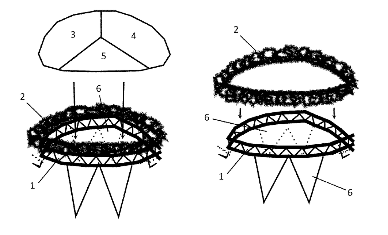
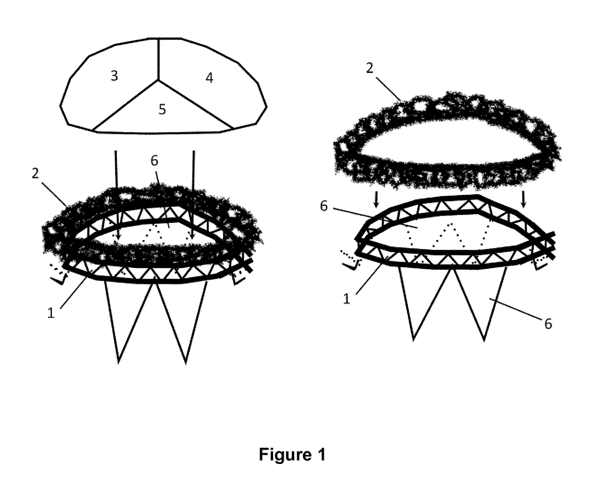
[0032]FIG. 1 shows a first embodiment of a prosthetic mitral valve according to the present invention comprising a stent (1) and a wire mesh (2) surrounding the stent at the atrial end and forming a body around the stent (2) which extends beyond the atrial end. The stent comprises internally three valve leaflets (3,4,5). Furthermore, the stent forms at its ventricular end a pair of capturing elements (6) which capture the native leaflets thus providing positioning guidance and anchoring / retention.

embodiment 2

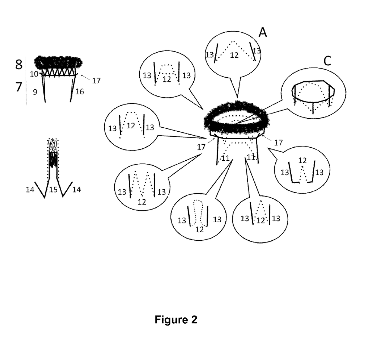
[0033]The endoprosthesis (FIG. 2) comprises of a plurality of leaflets, which consist of a natural and / or synthetic material and are being able to switch between their open and close position in response to the blood flow through the heart. The leaflets are attached into a collapsible wire valve frame that includes a stent (7) and a wire mesh (8). The frame has a body that defines a lumen to its inside. The exterior portion of the frame has features that serve for its conformation and stabilization / anchoring in the anatomic structures it contacts. When the endoprosthesis apparatus is expanded within the intended failing native heart valve it replaces it and resumes its function. The frame of the endoprosthesis includes a stent and a wire mesh. All these are also described in the embodiment 1.

[0034]The stent part of the endoprosthesis includes a crown (9), and a ring (10). The crown includes capturing elements for each of the native valve leaflets (11). Each such element has an exter...

embodiment 3

[0047]Another version (FIG. 4A) of the described in the embodiment 2 endoprosthesis can be deployed in the opposite way, starting from the atrial side (FIG. 4B, 4C, 4D). First, the wire mesh is gradually released within the left atrium (FIG. 4B, 4C). The valve then is pulled downward till the wire mesh seats firmly at the floor of the atrium. Then the stent ring (18) is released followed by its crown (19) that contains a plurality of anchoring structures (hooks, barbs, spikes, indentations or similar) (20) extending into the ventricular side of the annulus. Two of them may be seated and capture the fibrous trigones on both sides of the anterior leaflet and hold this leaflet wide-open. Another component of the crown may extend in the middle part of the posterior leaflet (21). This is longer and therefore the last to be completely released from the delivery system. Its final part folds completely backwards (22) towards the ventricular side of the annulus to capture the posterior leafl...


PUM


Abstract

A prosthetic heart valve for an endoprosthesis used in the treatment of a stenotic heart valve and/or a heart valve insufficiency. The prosthetic heart valve comprises a plurality of leaflets (3,4,5) which are able to switch between their open and close position in response to the blood flow through the heart. The leaflets are attached into a collapsible wire valve frame involving a stent part (1) and a wire mesh part (2) that complement each other in many ways. The prosthetic valve comprises additional elements (6) for its correct positioning and stabilization.

Description

FIELD OF THE INVENTION[0001]The invention generally relates to devices for cardiovascular treatment. More specifically, the invention generally relates to devices for percutaneous heart valve replacement / implantation.BACKGROUND OF THE INVENTION[0002]Valvular heart disease is common and involves considerable mortality and morbidity. Surgical replacement of the failing valve is the treatment of choice when the disease progresses and certain criteria are fulfilled. However, it is not uncommon patients fulfilling the criteria for this treatment to be rejected due to a perceived unacceptably high surgical risk for a variety of reasons such as advanced age and comorbidities. For some it is their decision to deny this treatment. These factors drove the development of prosthetic heart valve devices that can be implanted percutaneously with guiding catheters. Many such devices for the treatment of aortic valve stenosis have gained regulatory approvals and are already successfully and widely ...

Claims


Application Information

Patent Timeline
Patent Type & Authority Applications(United States)
IPC IPC(8): A61F2/24
CPCA61F2/2418A61F2220/0016A61F2210/0014A61F2/2436A61F2250/0063A61F2220/0008
Inventor SPARGIAS, KONSTANTINOS
Owner EDWARDS LIFESCIENCES CORP
Why Eureka
Try Eureka